Vehicle equipped with omni-directional wheels

a technology of omni-directional wheels and vehicles, which is applied in the direction of automatic initiation, braking systems, transportation and packaging, etc., can solve the problems of omni-directional wheels lacking stationary stability of vehicles, keeping vehicles stopped reliably, and vehicles with omni-directional wheels. achieve the effect of increasing the braking force during stopping of vehicles, simple configuration, and increasing the braking for

Pending Publication Date: 2022-04-07
TOYOTA JIDOSHA KK
View PDF0 Cites 0 Cited by
  • Summary
  • Abstract
  • Description
  • Claims
  • Application Information

AI Technical Summary

Benefits of technology

[0015]According to the first disclosure, the vehicle equipped with omni-directional wheels is provided with a moving mechanism that protrudes the grounding part from the bottom of the vehicle toward a ground surface. According to such a configuration, in the vehicle equipped with omni-directional wheels having a problem in the stop stability with respect to the lateral direction of the vehicle, it is possible to increase the braking force by grounding the grounding part to the ground.
[0016]According to the second disclosure, the moving mechanism is controlled so as to ground the grounding part to the ground surface when it detects that the vehicle has stopped.

Problems solved by technology

However, the omni-directional wheel has one aspect of lacking stationary stability of the vehicle in the lateral direction due to its structure.
For this reason, vehicles with omni-directional wheels have a problem in keeping the vehicle stopped reliably on unstable ground surfaces such as

Method used


Image

  • Vehicle equipped with omni-directional wheels
  • Vehicle equipped with omni-directional wheels
  • Vehicle equipped with omni-directional wheels

Examples


first embodiment

1. First Embodiment

1-1. Schematic Structure of Automated Traveling Pallet

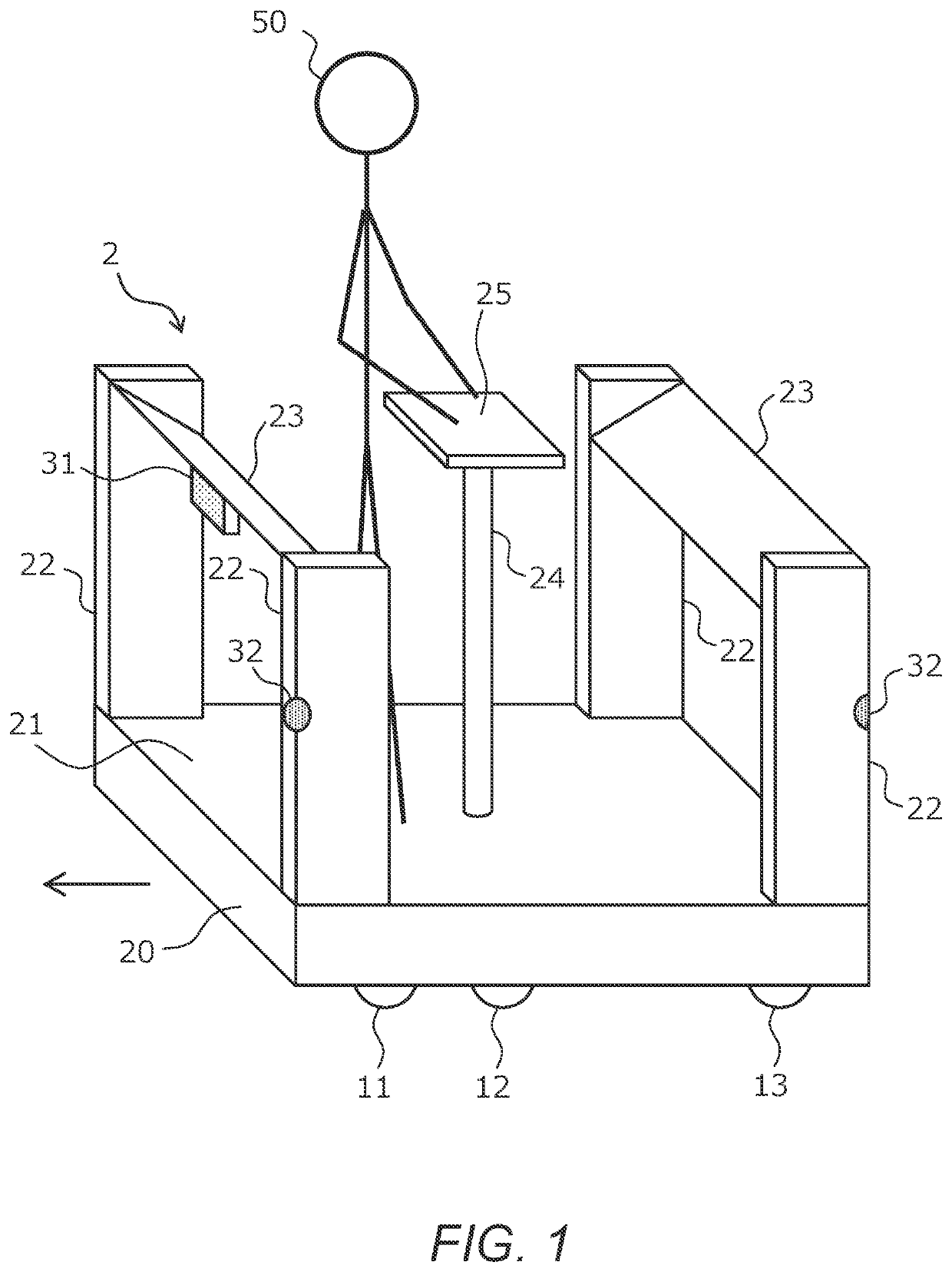
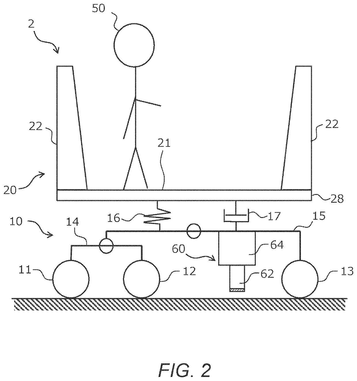
[0027]FIG. 1 is a diagram showing a schematic structure of an automated traveling pallet of the first embodiment. An automated traveling cart 2 according to the present embodiment is an automated traveling cart having a pallet-type vehicle body 20. In the following description, the automated traveling cart 2 according to the present embodiment is referred to as an automated traveling pallet.

[0028]The automated traveling pallet 2 is a low-floor vehicle whose height of a deck 21 of the vehicle body 20 is about 30 cm from the ground surface. At the bottom of the vehicle body 20, front wheels 11, middle wheels 12, and rear wheels 13 are provided on each side. These wheels 11, 12, 13 can make the automated traveling pallet 2 travel in either the left and right direction in FIG. 1. Here, the leftward direction is assumed to be a basic traveling direction of the automated traveling pallet 2 as indicated by an arrow in...

second embodiment

2. Second Embodiment

2-1. Features of Second Embodiment

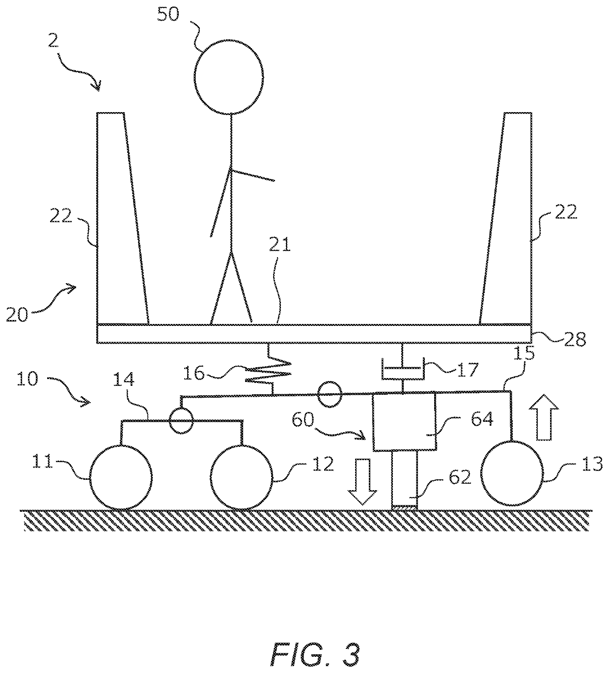
[0054]FIG. 6 is a diagram showing a schematic structure of an automated traveling pallet of the second embodiment. In FIG. 6, elements common to those of the automated traveling pallet 2 of the first embodiment shown in FIG. 1 are denoted by the same reference numerals, and descriptions thereof are omitted. The automated traveling pallet 2 of the second embodiment is characterized in that it includes a ride height adjusting mechanism 66 as the moving mechanism. The ride height adjusting mechanism 66 is installed on top of the rocker 15, the vehicle body 20 is mounted thereon. That is, in the automated traveling pallet 2 of the second embodiment, the ride height adjusting mechanism 66 and the damper 17 correspond to the suspension device connected between the spring upper structure and the spring lower structure. The ride height adjusting mechanism 66 includes an air bag and an electric compressor for feeding compressed air into t...


PUM


Abstract

A vehicle equipped with a plurality of omni-directional wheels includes a grounding part that supports the vehicle by grounding to a ground surface, a moving mechanism to protrude the grounding part from the bottom of the vehicle toward the ground surface, and a controller for controlling the moving mechanism so as to ground said grounding part to the ground surface. The controller is configured to control the moving mechanism so as to ground the grounding part to the ground surface when the vehicle is detected to have stopped.

Description

CROSS-REFERENCE TO RELATED APPLICATION[0001]The present application claims priority under 35 U.S.C. § 119 to Japanese Patent Application No. 2020-169399, filed Oct. 6, 2020, the contents of which application are incorporated herein by reference in their entirety.BACKGROUNDField[0002]The present disclosure relates to a vehicle equipped with omni-directional wheels and, in particular, to vehicle safety techniques having omni-directional wheels.Background Art[0003]Japanese Patent Application Laid-Open No. 2014-46890 discloses a technique related to an omni-directional movement cart equipped with omni-directional wheels. In this technology, the cart is instantaneously assisted in all directions by the power assist function by the omni-directional wheels.SUMMARY[0004]The omni-directional wheels are wheels that can move not only in the direction of wheel rotation (i.e., front-to-back direction of the vehicle), but also in the left-right direction of the vehicle. However, the omni-directio...

Claims


Application Information

Patent Timeline
IPC IPC(8): B60B19/00B60G17/016B60S9/205
CPCB60B19/003B62D51/02B60S9/205B60G17/016B60T1/14B60T7/12B60G17/0523B60G2202/152B60T2250/04B66F9/06B60B33/04B66F9/063B66F9/07509B66F9/0755B60G2500/30
Inventor ISHII, DAISUKESATO, DAISUKEIZU, HIROKIMORITA, HIROKISATO, KEINANAHARA, MASAKISERIZAWA, KAZUMITANAKA, HIRONOBUMOGI, SHUNSUKEHAYASHI, TAKASHIKUSUMOTO, AKIHIRO
Owner TOYOTA JIDOSHA KK
Why Eureka
Try Eureka