Ceramic vape assembly

Pending Publication Date: 2022-04-14
JUPITER RES LLC
View PDF0 Cites 0 Cited by
  • Summary
  • Abstract
  • Description
  • Claims
  • Application Information

AI Technical Summary

Benefits of technology

The present technology relates to vaporizer devices, which are used to vaporize plant-based materials. These devices may have a tubular body with an atomizer inside it, which heats up and vaporizes the material. The vaporizer may have a seal to contain the material and a connected battery to power the atomizer. The technical effects of this technology include improved vaporization efficiency, greater portability, and reduced power consumption.

Problems solved by technology

However, a conventional vaporizer device is configured in a manner that does not allow the oil to feely flow to the heated coil.
Accordingly, a conventional vaporizer device is prone to leaving an oily residue in the chamber after repeated use, which may result in unpleasant flavors and aromas.

Method used


Image

  • Ceramic vape assembly
  • Ceramic vape assembly
  • Ceramic vape assembly

Examples


Embodiment Construction

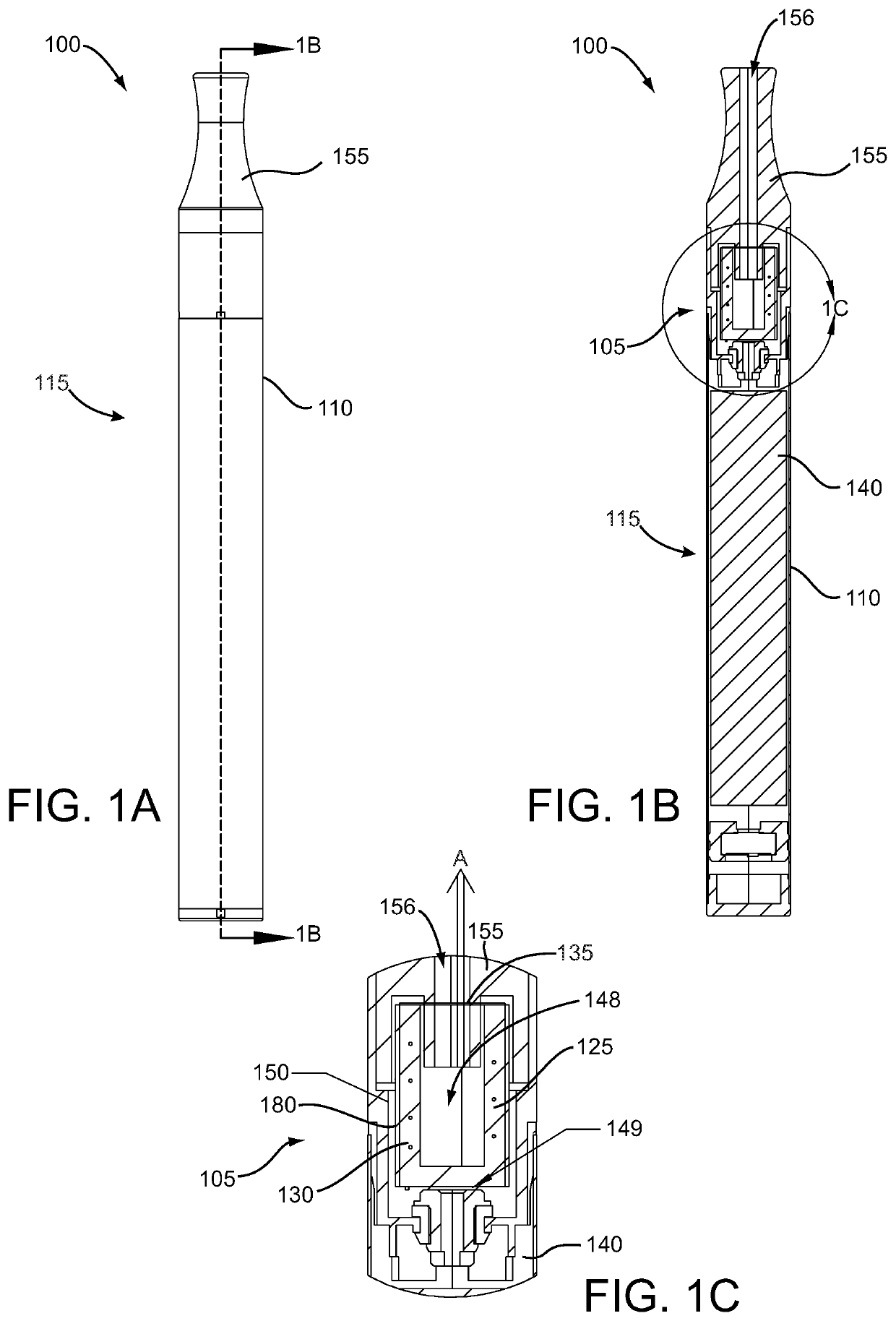
[0029]The present technology may be described in terms of functional block components. Such functional blocks may be realized by any number of components configured to perform the specified functions and achieve the various results. For example, the present technology may employ various atomizers, batteries, airflow channels, circuitry, coils, heating elements, housings, inlets, locking components, positioning elements, mouthpieces, mouthpiece assemblies, outlets, power supplies, plugs, power terminals, seals, tubular bodies, vaporizer devices, wires, and the like, which may carry out a variety of functions. In addition, the present technology may be practiced in conjunction with any one of various vaporizer systems, and the vaporizer assembly described herein is merely one exemplary application for the technology.

[0030]Referring to FIGS. 1-7, in various embodiments, a vaporizer system 100 may comprise a vaporizer assembly 105 adapted to be inserted into a housing 110 of a vaporizer...


PUM


Abstract

Systems and apparatus for a vaporizer device according to various aspects of the present technology may comprise a vaporizer assembly and a battery. The vaporizer assembly may comprise a tubular body comprising an outer surface and an inner surface defining a receptacle cavity in the tubular body. The vaporizer assembly may also comprise an atomizer at least partially disposed within the tubular body, wherein the inner surface and the atomizer define an inner volume in the tubular body. The vaporizer assembly may further comprise a seal configured to contain a vaporizable material inside the inner volume and a heating element coupled to the atomizer. The battery may be connected to the heating element.

Description

CROSS-REFERENCE TO RELATED APPLICATION[0001]This application claims the benefit of U.S. Provisional Patent Application Ser. No. 63 / 089,161, filed on Oct. 8, 2020, and incorporates the disclosure of the application in its entirety by reference.BACKGROUND OF THE INVENTIONState of the Art[0002]Vaporizer devices present an alternative to smoking and work by vaporizing a consumable flower or oil, such as cannabis, tobacco, etc. by heating the flower or oil at a lower temperature than an open flame so that a user can inhale the flower or oil in vapor form, rather than smoke.[0003]A conventional vaporizer device typically has a chamber for holding oil, a small, heated coil in contact with the chamber, and one or more openings to allow a user to draw vapor toward the mouth of the user. A current is typically passed through the coil, thereby heating the chamber which in turn heats the oil. However, a conventional vaporizer device is configured in a manner that does not allow the oil to feely...

Claims


Application Information

Patent Timeline
IPC IPC(8): A24F40/42A24F40/46A24F7/02
CPCA24F40/42A24F7/02A24F40/46
Inventor LI, SANSCATTERDAY, MARK
Owner JUPITER RES LLC
Why Eureka
Try Eureka