
Eureka
For R&D, Eureka makes reading and utilizing patents & technical documents easy.
Eureka AIR
Designed for self-driven R&D workflows. Generate viable solutions, solve complex R&D challenges, empower your innovation with AI.

Eureka Materials
Designed for material experts only. Revolutionize your material R&D, from search, analyze, to developing new materials.

TechResearch
Generate reliable direction feasibility study reports for your R&D in just a few steps.

TechSeek
Discover and master advanced knowledge NOW. Basics, ideas, possibilities, all at once.

TechMind
As an expert in R&D Theories, TechMind can generates customized viable solutions instantly.

TechRisk
Analyze your overall solution with one click, know your potential R&D risks in advance.

TechMonitor
Get weekly tech updates, stay abreast of the latest tech innovations and key insights.
Imaging Apparatus and Imaging Method
- Summary
- Abstract
- Description
- Claims
- Application Information
AI Technical Summary
Benefits of technology
Problems solved by technology
Method used
Image

Examples
first embodiment
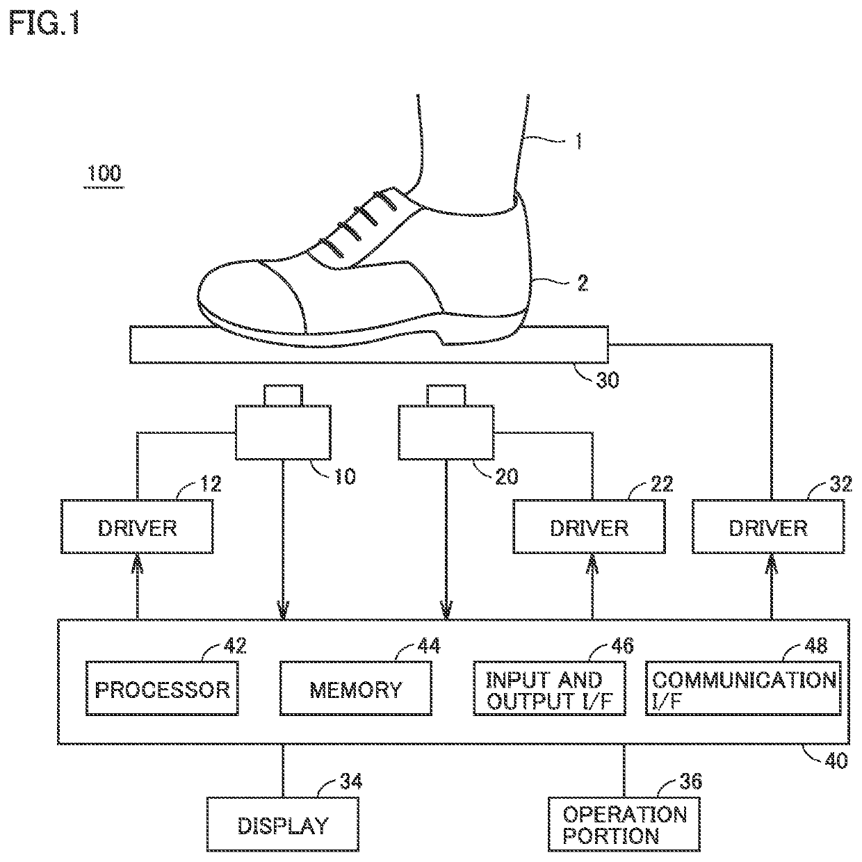
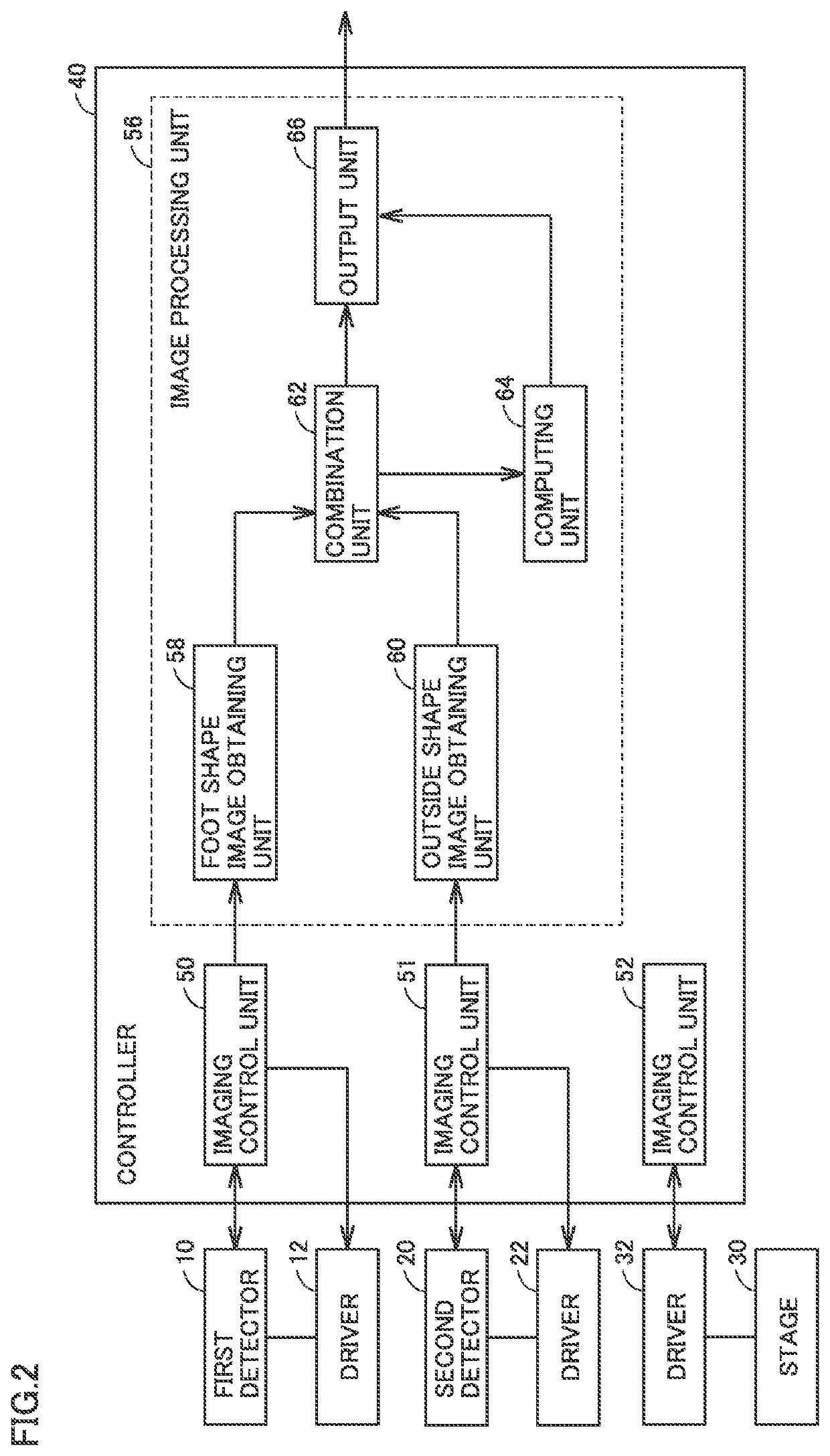
[0028]FIG. 1 is a diagram showing a schematic configuration of an imaging apparatus 100 according to a first embodiment. Imaging apparatus 100 according to the first embodiment is configured to image a target portion of a subject with his / her apparel on. “Apparel” herein is a collective denotation of covering that covers and wraps each part of a human body for a wearing purpose and encompasses clothing, shoes, and headwear. In an example in FIG. 1, imaging apparatus 100 according to the first embodiment is configured to image a foot 1 of a subject with his / her shoe 2 on. In other words, in the exemplary configuration in FIG. 1, shoe 2 is defined as the apparel and foot 1 of the subject is defined as the target portion. The target portion includes at least the toe and the heel of foot 1.
[0029]As shown in FIG. 1, imaging apparatus 100 includes a first detector 10, a second detector 20, a stage 30, drivers 12, 22, and 32, a controller 40, a display 34, and an operation portion 36.
[0030...
second embodiment
[0075]In the first embodiment above, a configuration in which a passive imaging technique to image a shape of a foot in the inside of a shoe by detecting terahertz light radiated from the foot is used for a foot shape imager that obtains a foot shape image is described. In second to fourth embodiments, a configuration in which an active imaging technique to image a shape of a foot in the inside of a shoe by irradiating the shoe with terahertz light at an already-known frequency and detecting transmitted light or reflected light thereof will be described. Initially, in the second embodiment, an exemplary configuration in which the active imaging technique using transmitted light from a shoe will be described.
[0076]FIG. 5 is a diagram showing a schematic configuration of imaging apparatus 100 according to the second embodiment. As shown in FIG. 5, imaging apparatus 100 according to the second embodiment includes stage 30, a light source 70, a detector 80, drivers 32, 72, and 82, contr...
third embodiment
[0102]In a third embodiment, a first exemplary configuration in which the active imaging technique using reflected light from shoe 2 is employed will be described.
[0103]FIG. 11 is a diagram showing a schematic configuration of imaging apparatus 100 according to the third embodiment. As shown in FIG. 11, imaging apparatus 100 according to the third embodiment includes stage 30, light source 70, detectors 20 and 81, drivers 22, 32, 72, and 82, controller 40, display 34, and operation portion 36. Imaging apparatus 100 according to the third embodiment is different from imaging apparatus 100 according to the first embodiment in including light source 70, first detector 81, and drivers 72 and 82 instead of first detector 10 and driver 12. Since the third embodiment is otherwise identical in configuration to the first embodiment, description will not be repeated.
[0104]Light source 70 generates terahertz light. Light source 70 is arranged to include at least shoe 2 within a range of irradi...
PUM
 Abstract
Description
Claims
Application Information
 - R&D Engineer
- R&D Manager
- IP Professional
- Industry Leading Data Capabilities
- Powerful AI technology
- Patent DNA Extraction
Browse by: Latest US Patents, China's latest patents, Technical Efficacy Thesaurus, Application Domain, Technology Topic, Popular Technical Reports.
© 2024 PatSnap. All rights reserved.Legal|Privacy policy|Modern Slavery Act Transparency Statement|Sitemap|About US| Contact US: help@patsnap.com