
Belt Driven Pedal Cycle Employing a Slim Protective Belt Drive Cover

a pedal cycle and drive cover technology, applied in guards, bicycle equipment, transportation and packaging, etc., can solve the problems of reducing lubrication, requiring oil lubrication to run efficiently, and reducing lubrication, so as to improve the prevention of riding clothing and reduce the cost

Pending Publication Date: 2022-04-21
KARBON KINETICS LLC
View PDF0 Cites 0 Cited by
  • Summary
  • Abstract
  • Description
  • Claims
  • Application Information

AI Technical Summary

Benefits of technology

The patent describes a new solution to protect the rider from trapping their clothes between the belt and sprocket. The solution is a slim protective belt drive cover that is compact, visually appealing, and lightweight. The cover follows the non-toothed perimeter surface of the belt and has a minimal clearance gap between the belt and the cover. The cover does not enclose the belt, allowing for adjustment of sprocket centers while ensuring the belt runs smoothly. This design is lighter, more compact, and visually appealing than traditional protective chain covers. The cover has a split two-part nature, making it easy to access the belt drive.

Problems solved by technology

However, bicycle roller chains have certain disadvantages such as requiring oil lubrication to run efficiently and also to prevent corrosion and rust.
Over time, the lubrication will diminish through usage and weather conditions such as rain at which point, unless the chain is re-lubricated, the chain with rust or corrode and will tend to produce more noise even to the point of squeaking.
Another problem with linked roller type chains is tendency for the riders clothing to become trapped or drawn into the interface between the teeth of the driven and driving sprockets and the chain.
This overlapped has the drawback of essentially doubling the thickness of the protective chain cover wall section and therefore the protective chain cover is required to be even larger beyond the outer perimeter of the chain drive when viewed from the side.
However, with regards to the field of pedal operated cycles such as bicycles, belt drives have certain drawbacks when compared to linked roller chains.
Another drawback of belt drives compared to linked roller type chains is that they are wider.
This can prove problematic for designers in that the critical so called “chain line” of the bicycle requires careful consideration in order to have sufficient clearance between the belt drive and the rear tyre, the frame and gear components and also be positioned for ergonomic and efficient, comfortable pedal crank operation.
Belt drives are not suitable for multi-speed derailleur gearing systems due to the fact that they are not laterally compliant, they are of fixed length, and require precise tension to operate efficiently.
Belt drives also suffer from the same problem as linked roller chains of the possibility for the rider's clothing to become trapped between the belt and the sprockets.
Whilst the popularity of belt drives is increasing, designers have not widely addressed this key drawback by adding a protective belt cover.
The main reason for this is that due to the greater width of the belt compared to the linked roller chain, a protective belt drive cover of the traditional design variety used on linked roller chain bicycle becomes too large and bulky to be commercially appealing.
The need to join the cover with an overlap joint further increases the size of the cover and has the drawback of trapping water within the cover.
Furthermore, joined up enclosed covers can resonate more noise than open covers.
This results in an even larger protective belt cover than traditional protective chain covers and is generally accepted as undesirable to the rider, being visually bulky and unappealing, adding undesirable cost, and adding undesirable weight.

Method used


Image

  • Belt Driven Pedal Cycle Employing a Slim Protective Belt Drive Cover
  • Belt Driven Pedal Cycle Employing a Slim Protective Belt Drive Cover
  • Belt Driven Pedal Cycle Employing a Slim Protective Belt Drive Cover

Examples


Embodiment Construction

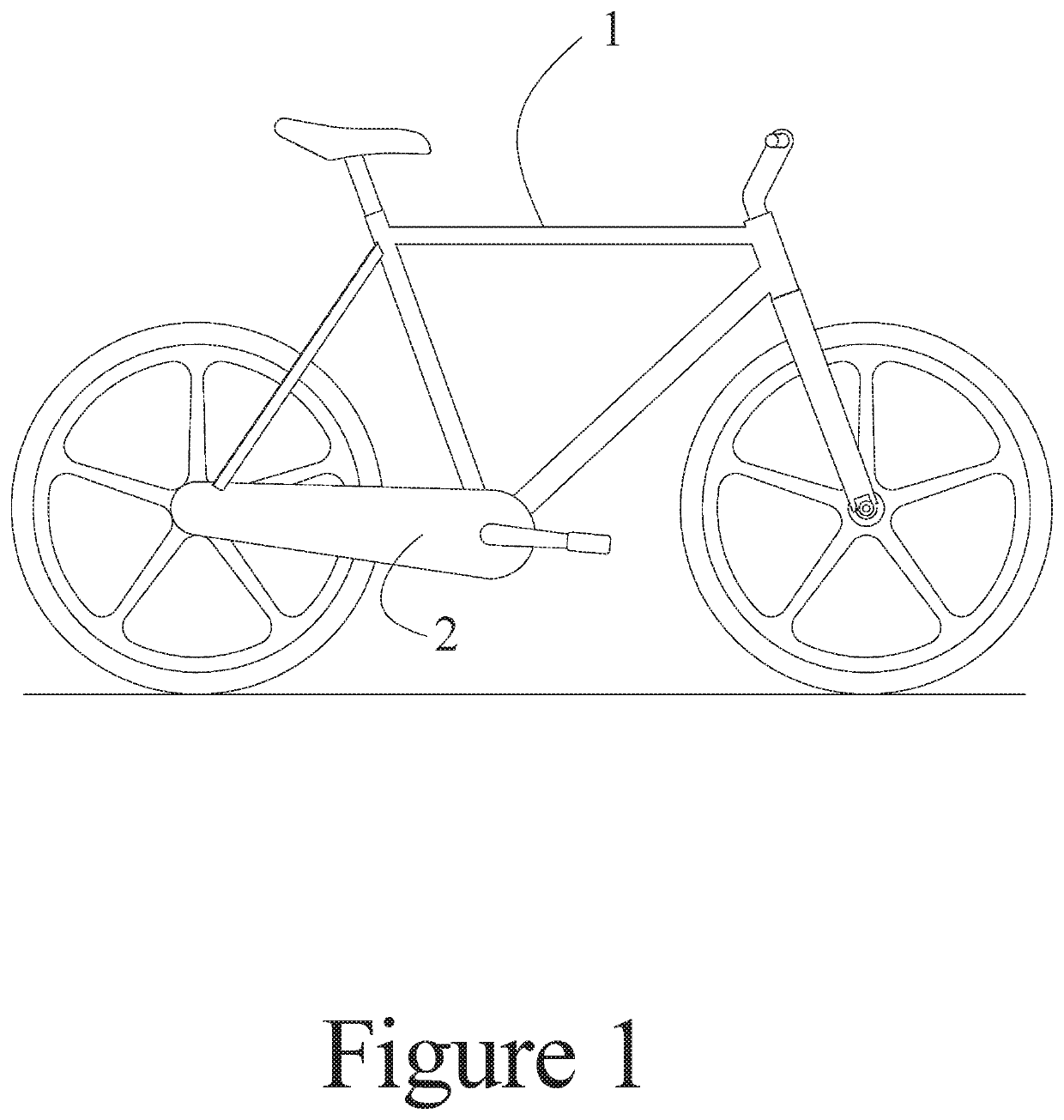
[0031]FIG. 1 shows a first embodiment comprising a belt driven pedal cycle 1 and a slim protective belt drive cover 2.

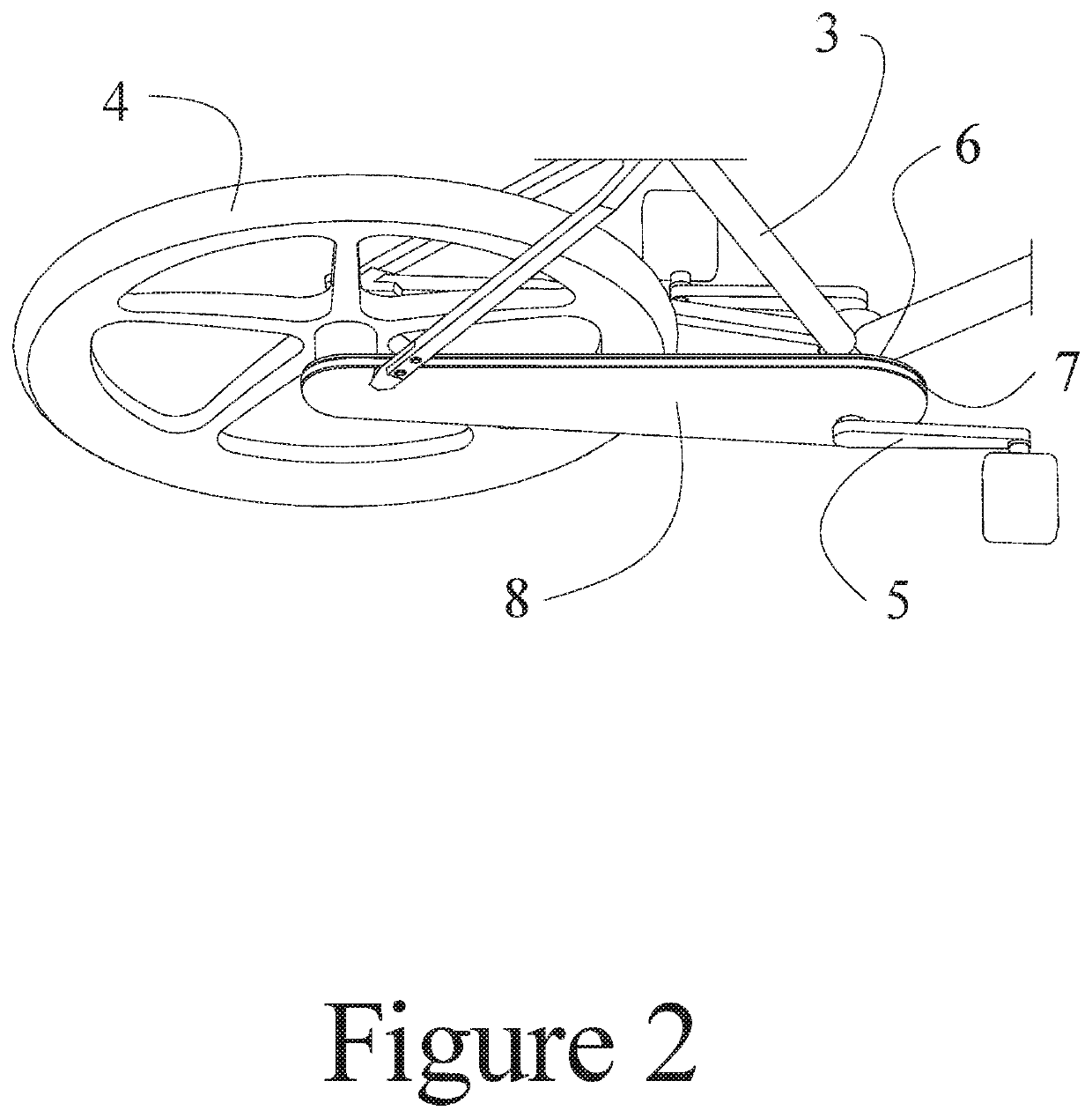
[0032]As shown in the perspective view of FIG. 2, the illustrated embodiment comprises a bicycle frame 3 fitted with a rear hub wheel assembly 4, a pedal crank assembly 5, an inner belt cover 6, an outer belt cover 8 and a belt drive 7 such that power rotatably input through pedal crank assembly 5 is transmittable to rear hub wheel assembly 4 through belt drive 7. Inner belt cover 6 and outer belt cover 8 may be made from materials such as plastic, metals, or composites and could be manufactured through injection moulding, forming, or other pressure type moulding processes for example. Inner belt cover 6 and outer belt cover 8 are not essential for the structural integrity of bicycle frame 3 in the embodiment presented in FIG. 2.

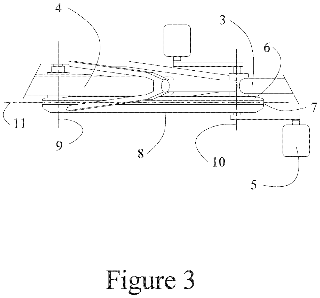
[0033]As shown in FIG. 3, the illustrated embodiment comprises a bicycle frame 3 fitted with a rear hub wheel assembly 4 rotatable about a r...


PUM


Abstract

A pedal driven cycle comprising a belt drive connecting a power input sprocket to a driven sprocket along a chain line; an outer protective belt drive cover plate having a footprint which substantially coincides with a side profile of the belt drive along at least a major portion of its length of travel so that the outer cover plate does not extend beyond an outer surface of the belt drive; and fixtures for mounting the outer protective belt drive cover plate to the cycle in parallel with the chain line and laterally spaced apart from a side edge of the belt drive to provide a clearance, with fore and aft adjustment.

Description

BACKGROUND[0001]The vast majority of pedal driven cycles, bicycles for example, employ a metallic linked roller type chain to transmit power input by the rider through the pedal cranks to the rear wheel. The advantages of roller chains are well known and include being highly efficient, durable, compact and relatively low cost. Other advantages of the linked roller type chain are that they are able to operate efficiently over a wide range of tensions between the sprockets as well as being highly flexible laterally and thus are able to be used in combination with well understood multi-speed derailleur gearing systems. However, bicycle roller chains have certain disadvantages such as requiring oil lubrication to run efficiently and also to prevent corrosion and rust. Over time, the lubrication will diminish through usage and weather conditions such as rain at which point, unless the chain is re-lubricated, the chain with rust or corrode and will tend to produce more noise even to the p...

Claims


Application Information

Patent Timeline
IPC IPC(8): B62J13/06
CPCB62J13/06B62J13/00B62M9/02B62M1/36
Inventor THORPE, RICHARD
Owner KARBON KINETICS LLC
Learn More