Improved system for reporting aircraft runway conditions

Pending Publication Date: 2022-04-21
HYDRO AIRE INC
View PDF6 Cites 0 Cited by
  • Summary
  • Abstract
  • Description
  • Claims
  • Application Information

AI Technical Summary

Benefits of technology

The present invention is an aircraft runway condition monitoring unit that works with the aircraft's anti-skid / brake control system to provide a report of the aircraft's braking response to the current runway conditions from touchdown to a safe taxiing ground speed. The unit receives data from the aircraft brake control unit and may also incorporate data from sensors like GPS and dedicated accelerometers to improve accuracy. The objective report can be sent to the flight deck, air traffic control tower, and management team for future reference. The technical effect is to enhance the pilot's ability to prepare for and perform troublesome landings by providing valuable information about the current runway conditions.

Problems solved by technology

While aircraft travel is considered among the safest modes of transportation, there are elements of air travel that remain a challenge.
Each year there are numerous cases of commercial aircraft landing or taxiing in poor weather conditions on runways affected by adverse runway conditions that result in problems with the landing or control of the aircraft.
A major contributor to these events is a difficulty for the pilot to establish enough braking friction on wet or frozen wheels / runways to safely bring the aircraft to a controlled stop.
This can lead to overrunning of the runway or other hazardous situations that are perilous for the aircraft and / or the passengers.
Since these evaluations are primarily subjective and based on pilot evaluating, these subjective criteria often vary from pilot to pilot and can be unreliable for various reasons, including whether a pilot is not willing to admit that a landing was challenging or risky.

Method used


Image

  • Improved system for reporting aircraft runway conditions
  • Improved system for reporting aircraft runway conditions
  • Improved system for reporting aircraft runway conditions

Examples


Embodiment Construction

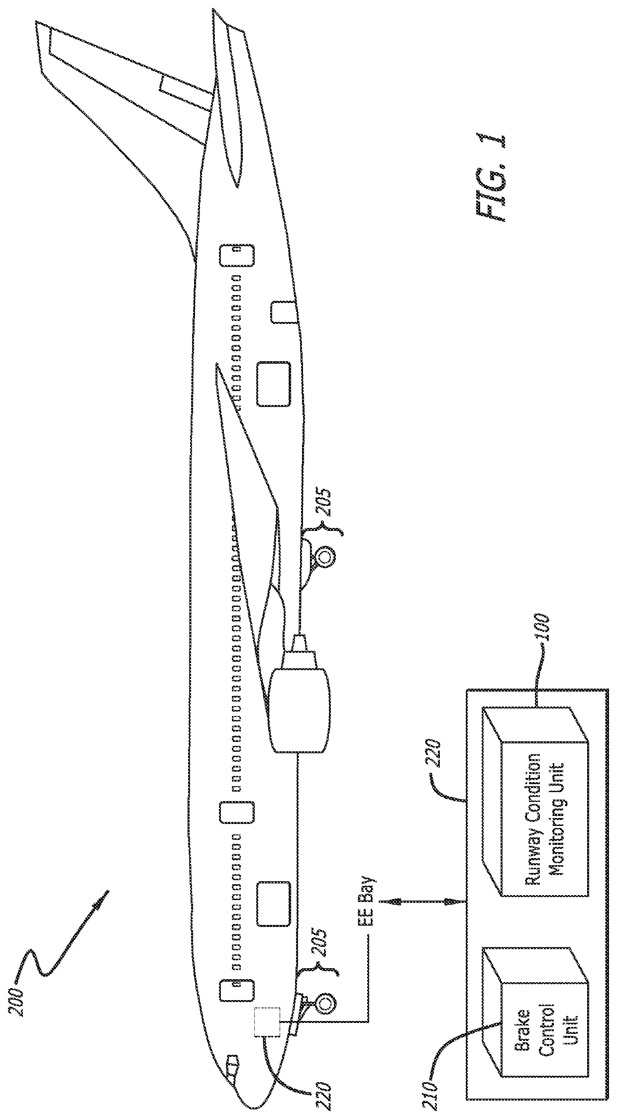
[0012]FIG. 1 illustrates a commercial aircraft 200 with a conventional landing gear 205 that is connected to and controlled by a brake control unit 210 in the aircraft electronics bay 220. The brake control unit 210 receives signals from the various sensors at the landing gear 205. The present invention introduces a new runway condition monitoring unit 100 to receive data and receive data from the brake control unit 210 to improve the evaluation of an aircraft runway and improve the dissemination of the evaluation to various clients.

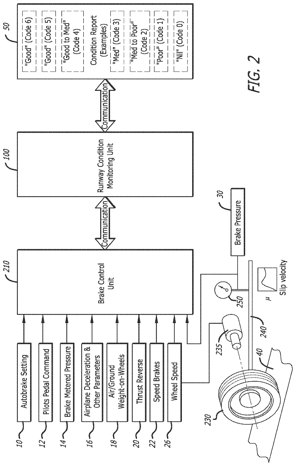
[0013]FIG. 2 illustrates a schematic diagram of some of the various inputs that are utilized to generate a report that objectively assesses a landing condition in the present invention. The aircraft 200 has multiple landing gear wheels 230 that are mounted on its axle 235, which supports a brake line 240. A sensor 250 measures the brake pressure applied to the wheel, and this measured data is communicated to the brake control unit 210. Other inputs to th...


PUM


Abstract

The present invention combines known brake control systems with a new runway condition monitoring unit that works in conjunction with an anti-skid / brake control unit to improve runway condition evaluation. The runway condition monitoring unit is installed on an airplane and receives data from the brake control unit, and processes that data through hardware and software to formulate a runway condition report of the airplane while landing on a runway. The invention may include additional sensors or interfaces that supplement the data received from the BCU. The runway condition monitoring unit contains a processor and interfaces that calculates and creates a runway condition report. The runway condition monitoring unit communicates the report by way of the avionics communication network on the airplane to devices that then send the runway condition report to consumers of the data; such as the flight deck, air traffic controllers, airport operators and airline operations.

Description

CROSS-REFERENCES TO RELATED APPLICATIONS[0001]This application claims priority to U.S. Application No. 63 / 093,493, filed Oct. 19, 2020, the content of which is fully incorporated herein by reference.BACKGROUND[0002]While aircraft travel is considered among the safest modes of transportation, there are elements of air travel that remain a challenge. One of the most critical aspects of travel by aircraft is the landing, and more particularly, landing in inclement weather. Each year there are numerous cases of commercial aircraft landing or taxiing in poor weather conditions on runways affected by adverse runway conditions that result in problems with the landing or control of the aircraft. A major contributor to these events is a difficulty for the pilot to establish enough braking friction on wet or frozen wheels / runways to safely bring the aircraft to a controlled stop. This can lead to overrunning of the runway or other hazardous situations that are perilous for the aircraft and / or...

Claims


Application Information

Patent Timeline
IPC IPC(8): G08G5/00G07C5/08G07C5/00B64C25/42B60T8/17
CPCG08G5/0013G07C5/0841B60T2210/10B64C25/42B60T8/1703G07C5/008B60T8/172G08G5/0026G08G5/025B64C25/426
Inventor RABY, RONALDPASHAIAN, LEOPAZ, ILAN
Owner HYDRO AIRE INC
Why Eureka
Try Eureka