
Hair transplanter having core shaft conveying portion

Pending Publication Date: 2022-05-05
OHDAE CORP
View PDF0 Cites 0 Cited by
  • Summary
  • Abstract
  • Description
  • Claims
  • Application Information

AI Technical Summary

Benefits of technology

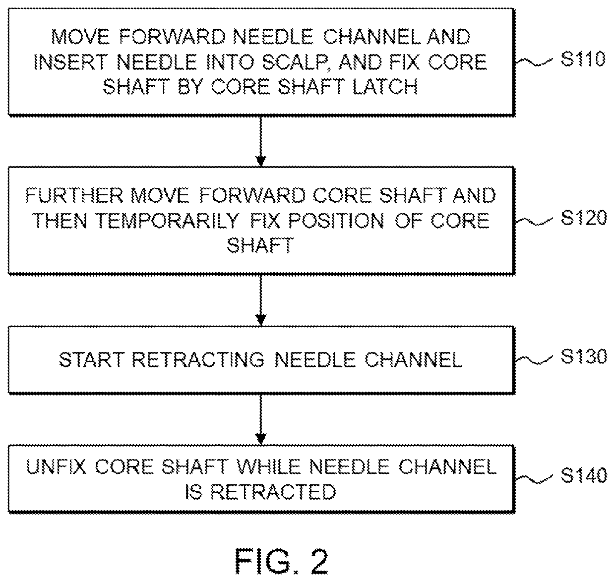
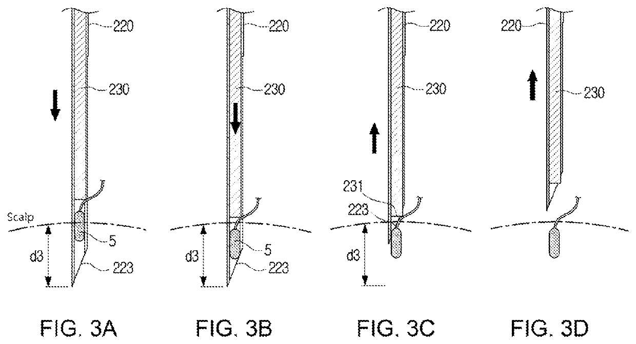
This patent describes a hair transplantation device that reduces the damage to the patient's scalp and reduces bleeding during the procedure. The device achieves this by reducing the penetration depth of the needle and by stopping the core shaft for a moment to securely implant the hair follicle. This results in a higher success rate of the procedure and reduces the likelihood of complications.

Problems solved by technology

However, in the case of the automatic hair transplanter, when the needle is moved forward by the motor, the needle may move forward at a relatively slow speed and may not pierce a scalp in a single time due to resistance of the scalp.
In order to prevent this problem, a user should strongly hold the hair transplanter and there is a problem that much force is required to operate.
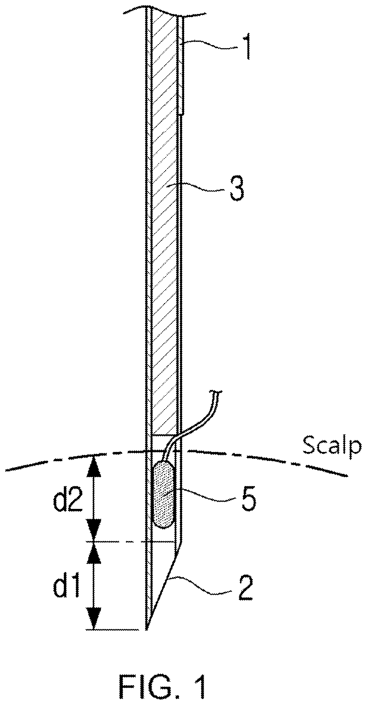
According to the needle structure described above, if the hair follicle 5 protrudes toward the inclined surface 2, the air follicle 5 may rub against the scalp when the needle is inserted into the scalp, and there is a problem that the hair follicle is destroyed.
As a result, the needle 1 should be further inserted into the scalp by the length d1 of the inclined surface 2 of the needle in addition to the length d2 of the hair follicle, and a safety problem of a patient such as a damage to the scalp, bleeding, etc. may increase.

Method used


Image

  • Hair transplanter having core shaft conveying portion
  • Hair transplanter having core shaft conveying portion
  • Hair transplanter having core shaft conveying portion

Examples


Embodiment Construction

[0033]Exemplary embodiments will now be described more fully with reference to the accompanying drawings to clarify aspects, other aspects, features and advantages of the present disclosure. The exemplary embodiments may, however, be embodied in many different forms and should not be construed as limited to the exemplary embodiments set forth herein. Rather, the exemplary embodiments are provided so that this disclosure will be thorough and complete, and will fully convey the scope of the application to those of ordinary skill in the art.

[0034]It will be understood that when an element is referred to as being “on” (or “under”, “on the right of”, or “on the left of”) another element, the element can be directly on (or “under”, “on the right of” or “on the left of”) another element or a third element therebetween.

[0035]The expressions such as “upper”, “lower”, “left”, “right”, “front”, “rear”, etc. used in the specification to explain a position relationship between elements do not me...


PUM


Abstract

A hair transplanter includes: a needle channel bundle including a center shaft, and a plurality of needle channels coupled to an outer circumference of the center shaft to be slidable up and down; a first spring configured to push down and move forward one of the plurality of needle channels; and a second spring configured to retract the needle channel, which moves forward, in an upward direction, wherein each of the needle channels includes a body portion having a tubular inner space, a needle coupled to a lower portion of the boy portion, and a core shaft disposed in the tubular inner space to be slidable.

Description

[0001]This application claims priority to Korean Patent Application No. 10-2020-0143497 filed on Oct. 30, 2020, and all the benefits accruing therefrom under 35 U.S.C. § 119, the content of which in its entirety is herein incorporated by reference.BACKGROUND1. Field[0002]The present disclosure relates to a hair transplanter, and more particularly, to a bundle type hair transplanter having a plurality of hair transplantation needles mounted therein in a bundle type.2. Description of the Related Art[0003]A hair transplanter is a medical device that is used for a hair therapy procedure for transplanting hair by harvesting hair follicles from a hair growth area of a scalp and implanting the hair follicles into a bald scalp. A related-art hair transplanter includes a needle (referred to as a “transplantation needle” or a “needle”) and a core shaft slidably inserted into the needle, and a bundle type hair transplanter having a plurality of needle channels mounted therein and each includin...

Claims


Application Information

Patent Timeline
IPC IPC(8): A61B17/34
CPCA61B17/3468A61B2017/00398A61B17/3421A61B2017/00752A61F2/10A61F2220/0008A61B2017/00367
Inventor KIM, BYOUNG SULLEE, TAE SEONG
Owner OHDAE CORP
Learn More