
Solar-driven membrane-based open-cycle adsorption air conditioner

a solar energy and open-cycle technology, applied in the field of air conditioners, can solve the problems of unable to power the solutions of non-renewable energy sources, unable to meet the needs of renewable energy sources, and unable to meet the needs of low-cost, low-cost solutions

Pending Publication Date: 2022-05-05
OHIO STATE INNOVATION FOUND
View PDF0 Cites 0 Cited by
  • Summary
  • Abstract
  • Description
  • Claims
  • Application Information

AI Technical Summary

Benefits of technology

The patent describes an air conditioner system that can regulate the temperature and humidity of the air inside it. The system uses a metal organic frameworks-based heat and mass exchanger to remove moisture from the air and a solar heater to heat the air. The hot air is then used to regenerate the exchanger to prepare it for the next cycle of moisture removal. This technology allows for efficient air conditioning in a compact space.

Problems solved by technology

Air conditioning accounts for 5% of the United States' energy expenditure and 45% of peak summer electrical demand, and offers few system level opportunities to shirt the load over multi-hour time scales.
This precludes the exclusive use of waste heat from condensers or other equipment, or the use of solar thermal heaters for regeneration.
Although both of these types of systems are more efficient than bare vapor-compression systems, non-renewable energy sources cannot yet power these solutions because the sorbents require too high of a regeneration temperature due to their shallow Type 3 water sorption isotherm.
Microbes which may be harmful to human health grow on cooling coils and drip pans of vapor compression systems.
Liquid absorbents are usually salt solutions which may be destructive to downstream components if carryover into the airstream occurs and thus filters with large pressure drops must be added after the liquid sorbent contactors.
Solid sorbent wheels become fouled over time by particulates in the air stream.

Method used


Image

  • Solar-driven membrane-based open-cycle adsorption air conditioner
  • Solar-driven membrane-based open-cycle adsorption air conditioner
  • Solar-driven membrane-based open-cycle adsorption air conditioner

Examples


Embodiment Construction

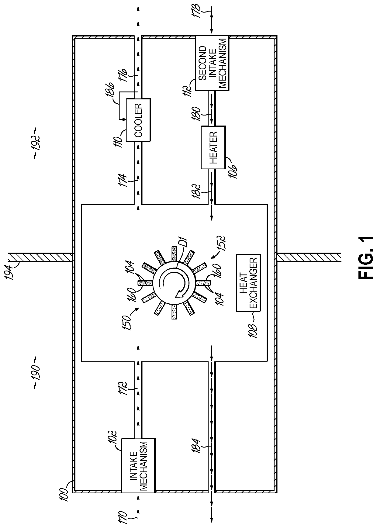
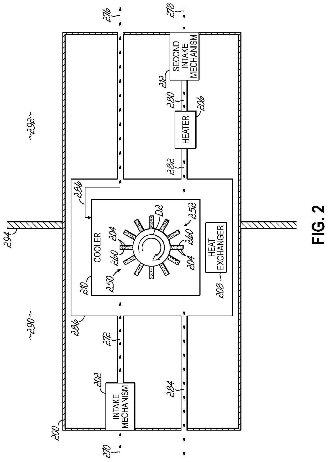
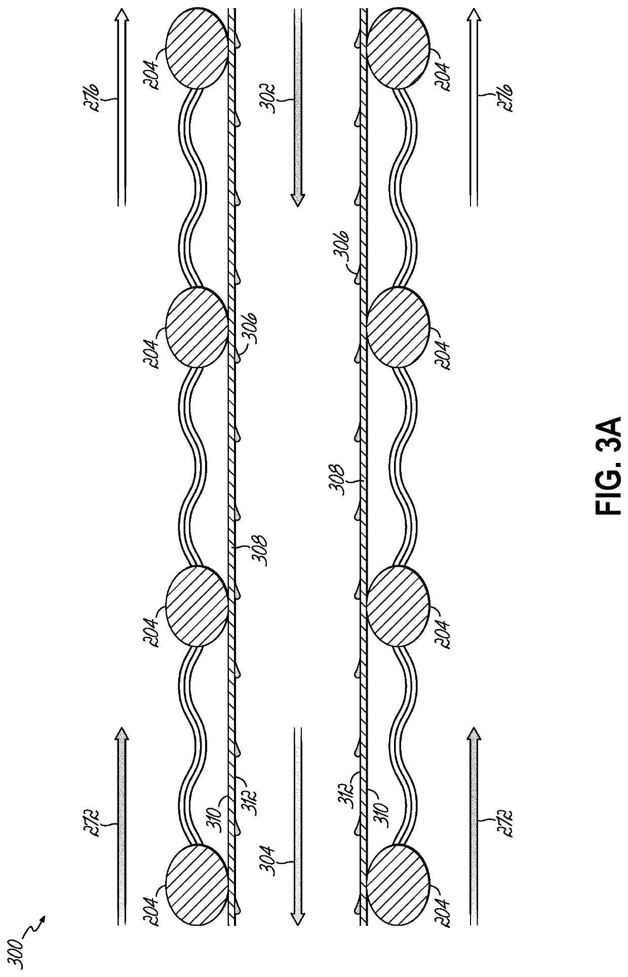
[0015]By way of an introductory example, an air conditioner including an intake mechanism configured to draw air and moisture into the air conditioners from an exterior of the air conditioner is provided. The air conditioner further includes a metal organic frameworks-based heat and mass exchanger in fluid communication with the intake mechanism, and the metal organic frameworks-based heat and mass exchanger configured to adsorb the moisture from the air drawn into the air conditioner. The air conditioner further includes a solar heater and a heat exchanger configured to together remove the moisture adsorbed by the metal organic framework, thus regenerating the metal organic framework.

[0016]One interesting feature of the systems and methods described below is that the air conditioner may use only heat supplied from the solar heater to regenerate the metal organic framework. Alternatively in addition, the air conditioner may avoid the use of less efficient air conditioner configurati...


PUM

PropertyMeasurementUnit
particle sizeaaaaaaaaaa
temperatureaaaaaaaaaa
pore diameteraaaaaaaaaa

Abstract

An air conditioning system and method of air conditioning is provided. The air conditioning system includes an intake mechanism configured to draw into the air conditioner a first amount of air and an amount of moisture from an exterior of the air conditioner. The system further includes metal organic frameworks in fluid communication with the intake mechanism, the metal organic frameworks configured to adsorb the amount of moisture from the first amount of air. The system further includes an indirect evaporative cooler configured to cool the first amount of air. The system further includes a solar heater configured to heat a second amount of air. The system further includes a heat exchanger configured to contact the second amount of air with the metal organic frameworks to regenerate the metal organic frameworks.

Description

CROSS-REFERENCE TO RELATED APPLICATIONS[0001]This application is an international application claiming priority to and benefits from the filing date of U.S. Provisional Application No. 62 / 806,863, filed Feb. 15, 2019, the entire contents of which is hereby incorporated by reference in its entirety. This application further claims priority to and benefits from the filing date of U.S. Provisional Application No. 62 / 835,763, filed Apr. 18, 2019, the entire contents of which is hereby incorporated by reference in its entirety.TECHNICAL FIELD[0002]This disclosure relates to air conditioners, and more particularly to adsorption, solar-driven air conditioners.BACKGROUND[0003]Air conditioning accounts for 5% of the United States' energy expenditure and 45% of peak summer electrical demand, and offers few system level opportunities to shirt the load over multi-hour time scales. Largely unchanged since its development in 1902, the vapor compression cycle used in the vast majority of air condi...

Claims


Application Information

Patent Timeline
Patent Type & Authority Applications(United States)
IPC IPC(8): B01D53/26F24F3/14F24S21/00F24F5/00B01D53/28B01D53/06B01J20/22B01J20/26B01J20/28B01J20/34
CPCB01D53/261B01D2257/80F24S21/00F24F5/0035B01D53/28B01D53/06B01J20/226B01J20/26B01J20/28026B01J20/28004B01J20/28033B01J20/3483B01J20/3425B01D2253/204F24F3/1411B01D2259/4508B01D2257/708B01D2258/06B01D53/0462Y02E10/40Y02B30/54
Inventor CLARK, JORDAN D.WADE, CASEYHO, W.S. WINSTON
Owner OHIO STATE INNOVATION FOUND
Learn More