Steel decarburization using carbon dioxide

a carbon dioxide and decarburization technology, applied in the field of decarburization of steel, can solve the problems of overheating the bath, affecting the yield of alloys, and accumulating a relatively high initial carbon amount, so as to reduce the oxygen level, enhance the yield of alloys, and reduce the oxygen consumption rate

Pending Publication Date: 2022-05-05
SABIC GLOBAL TECH BV
View PDF1 Cites 0 Cited by
  • Summary
  • Abstract
  • Description
  • Claims
  • Application Information

AI Technical Summary

Benefits of technology

[0010]A discovery has been found that provides a solution to at least some of the problems associated with steel making. The solution is premised on providing CO2 as an oxygen source during one or more stages of the steel making process. By way of example, CO2 can be provided as an oxygen source in an electric arc furnace (EAF) when it is difficult to provide sufficient effective amount of oxygen from the top. Without wishing to be bound by theory it is believed that addition of CO2 to the EAF can reduce the oxygen consumption rate and enhance the alloys addition yield due to the reduced oxygen level in the secondary processing (e.g., in the ladle furnace). In addition, the use of CO2 can lead to a more energy efficient process due to the reduction in Tap-To-Tap time. Furthermore, addition of the CO2 can start the decarburization of the steel at an early stage of the process.
[0011]In another example, CO2 can be provided to the ladle furnace and / or vacuum degassing step. Addition of the CO2 to the ladle furnace or the vacuum degassing unit can reduce the amount of oxygen required in the steel bath arriving the vacuum degassing unit to achieve the carbon target level. Furthermore, the use of CO2 / inert gas mix for stirring through a porous plug during the ladle furnace treatment can reduce the carbon level to a lower range for grades that do not require vacuum degassing treatment.

Problems solved by technology

At a low bath level, when the oxygen introduction performance using supersonic nozzle is minimal, a relatively high initial carbon amount can accumulate in the bath and can lead to boiling and / or reaction later during the process.
Furthermore, an excessive amount of oxygen can lead to overheating the bath, which affects the efficiency of the furnace.
Disruption of the carbon stream or inefficient carbon injection reduces the effectiveness of slag foaming.
The large distance which the conventional carbon injection stream must travel also reduces the velocity and energy with which it may penetrate the slag.
Another problem with carbon injection by lance is, when mixed externally from the melt and slag, the oxygen and carbon combine to produce a flame leaving less carbon to foam the slag and reduce FeO in the slag.
Thus, current steel making systems are not very efficient over much of the scrap-melting steel-making process and almost ineffective for many other conventional steel-making processes.

Method used


Image

  • Steel decarburization using carbon dioxide
  • Steel decarburization using carbon dioxide
  • Steel decarburization using carbon dioxide

Examples


Embodiment Construction

[0035]A discovery has been made that provides a solution to at least some of the problems associated with the reduction of the carbon content in steel (i.e., decarburization of the steel). The addition of CO2 can provide a more energy efficient process as it reduces the need for oxygen in one or more processing steps to produce steel.

[0036]These and other non-limiting aspects of the present invention are discussed in further detail in the following sections with reference to FIGS. 1-4.

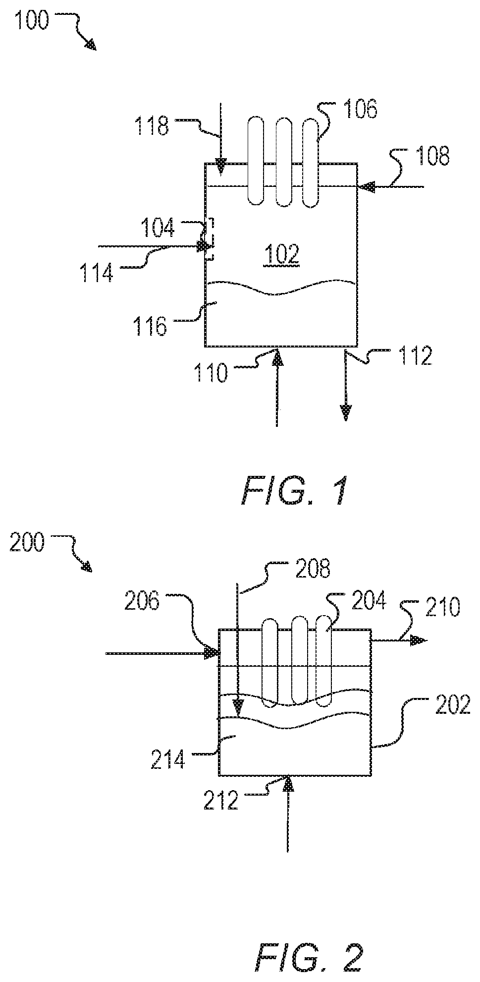
[0037]FIG. 1 depicts a schematic for a system to produce molten steel in an electric arc furnace (EAF). System 100 can include EAF 102, Iron-containing material inlet 104, electrodes 106, oxygen containing gas inlet 108, CO2 containing gas inlet 110, and molten steel outlet 112.

[0038]Iron-containing material 114 can enter EAF 102 through inlet 104. Iron-containing material can be any type of iron-based material (e.g., direct reduced iron (DRI, 80% Fe2O3), scrap metal, pig iron, etc.). In a preferred em...


PUM

PropertyMeasurementUnit
temperatureaaaaaaaaaa
temperaturesaaaaaaaaaa
wt. %aaaaaaaaaa

Abstract

Process to decarburize steel are described. A process can include contacting carbon dioxide with molten steel in an electric arc furnace, a ladle furnace, or a vacuum degassing unit, or a combination thereof.

Description

CROSS REFERENCE TO RELATED APPLICATIONS[0001]This application claims the benefit of priority of U.S. Provisional Patent Application No. 62 / 805,051, filed Feb. 13, 2019, which is hereby incorporated by reference in its entirety.FIELD OF THE INVENTION[0002]The invention generally concerns decarburization of steel. In particular, the invention concerns using carbon dioxide as an oxygen source for the decarburization of steel during one or more stages of steel making.BACKGROUND OF THE INVENTION[0003]Electric arc furnaces (EAFs) are used to make steel by using an electric arc to melt one or more charges of scrap metal placed in the furnace. In addition to the electrical energy of the arc, chemical energy is provided by auxiliary burners using fuel and an oxidizing gas to produce combustion products with a high heat content to assist the arc. In certain circumstances the scrap is dumped into the furnace through a roof opening from buckets which also may include charge carbon and slag form...

Claims


Application Information

Patent Timeline
Patent Type & Authority Applications(United States)
IPC IPC(8): C21D3/04
CPCC21D3/04C21C7/068C21C7/10C21C7/072C21C5/52Y02P10/20
Inventor AL-HARBI, MANSOUR
Owner SABIC GLOBAL TECH BV
Why Eureka
Try Eureka