Magnetic speed sensor with increased resolution

Active Publication Date: 2022-05-12
CONTINENTAL AUTOMOTIVE GMBH
View PDF0 Cites 0 Cited by
  • Summary
  • Abstract
  • Description
  • Claims
  • Application Information

AI Technical Summary

Benefits of technology

[0035]The benefit of an aspect of the present invention is obtained essentially at low engine speeds, such engine speeds implying a low number of identifications of angles of rotation of the tracked element driven by the internal combustion engine, especially when the target comprises only one tooth. Implementation of an aspect of the present invention at relatively hig

Problems solved by technology

With a prior-art sensor, at low engine speed, sufficient angles of rotation of the tracked element were not identified for implementation of a related function associated with t

Method used


Image

  • Magnetic speed sensor with increased resolution
  • Magnetic speed sensor with increased resolution

Examples


Embodiment Construction

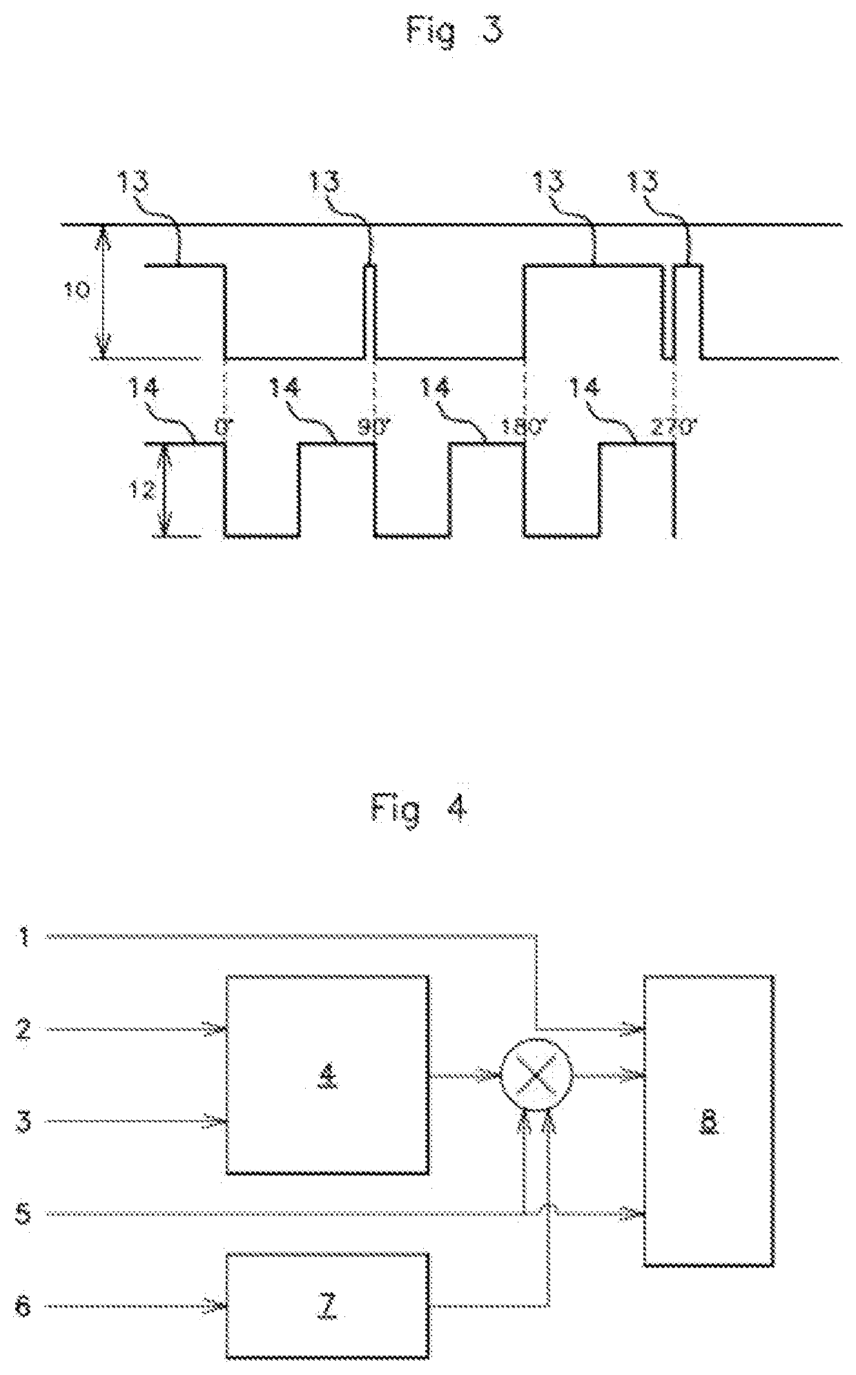
[0051]Below, reference is made to all the figures in combination. As regards recognition of designated reference numerals, when reference is made to one or more specific figures, these figures should be considered in combination with the other figures.

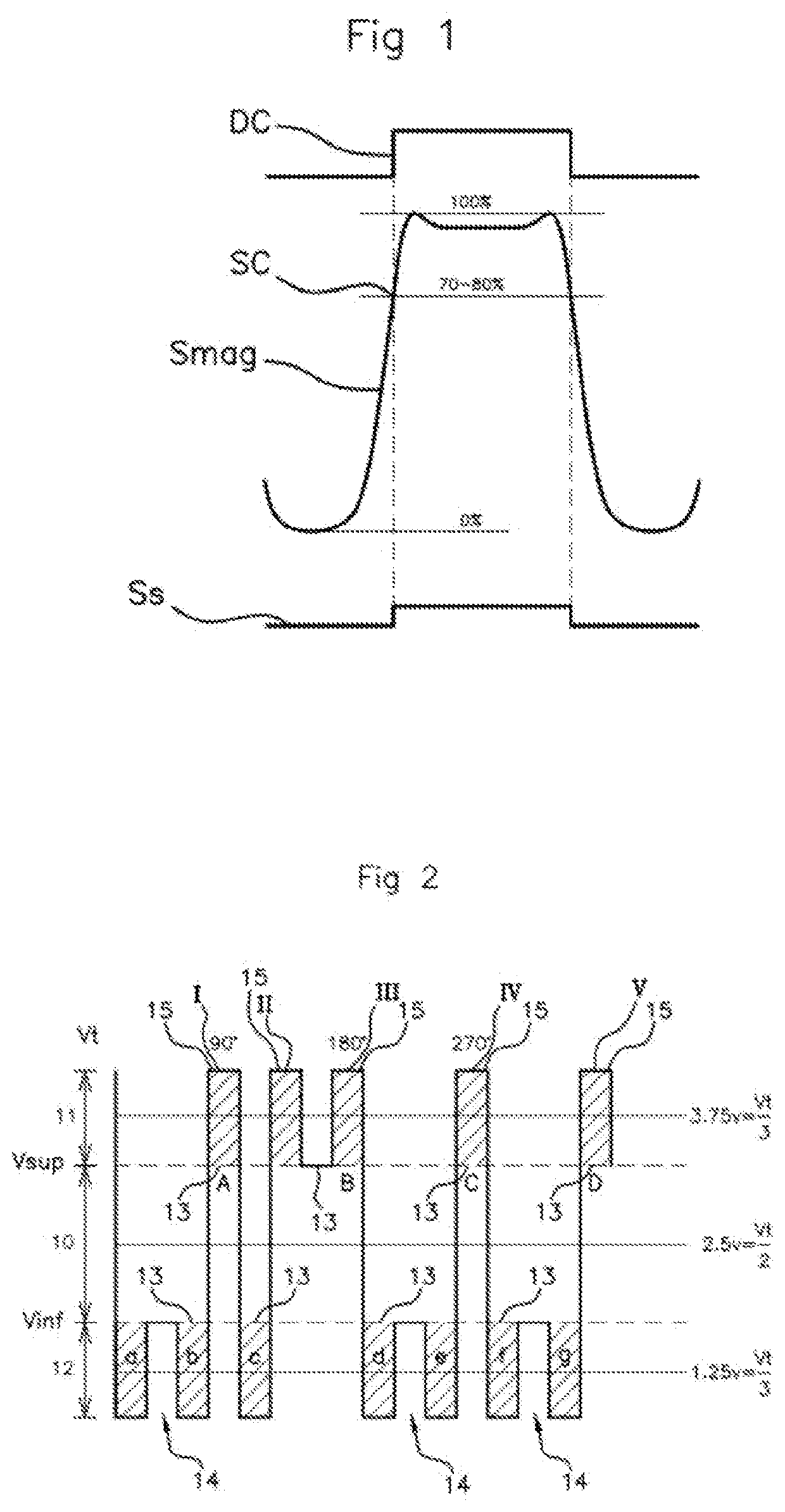
[0052]With reference to all the figures, and especially to FIGS. 1 and 2, an aspect of the present invention relates to a method for increasing a resolution of a magnetic sensor for an internal combustion engine of a motor vehicle, the sensor possibly being a camshaft sensor or a crankshaft sensor.

[0053]For such a magnetic sensor, a target comprising an alternating succession of teeth DC and of recesses is associated with an element driven by the internal combustion engine, for example the camshaft or crankshaft.

[0054]The magnetic-field sensor detects magnetic-field variations induced by a passage of the teeth DC of the target in proximity to the sensor, by generating a magnetic signal Smag, then periodically delivering an electrical o...


PUM


Abstract

A method for increasing a resolution of a magnetic sensor for an internal combustion engine of a motor vehicle. The sensor delivers an electrical synchronization signal having successive, spaced-apart crenels, one of the rising or falling edges of which corresponds to a respective angle of rotation of the element of the engine. A synchronization voltage range is interposed between an upper voltage modulation range above and a lower voltage modulation range below the upper and lower voltage of the synchronization range, respectively, the electrical signal in each of the lower and upper modulation ranges being modulated so as to include additional crenels, which are supplementary to the crenels of the synchronization signal, corresponding to periodic clock crenels with a period dependent on engine speed, an angle of rotation being identified by one of the rising or falling edges of each additional crenel.

Description

CROSS REFERENCE TO RELATED APPLICATIONS[0001]This application is the U.S. National Phase Application of PCT International Application No. PCT / EP2020 / 054941, filed Feb. 25, 2020, which claims priority to French Patent Application No. 1901956, filed Feb. 26, 2019, the contents of such applications being incorporated by reference herein.FIELD OF THE INVENTION[0002]The present invention relates to a magnetic sensor for detecting the speed of an element driven by an internal combustion engine with increased resolution, to a method for increasing the resolution of a magnetic sensor and to a method for controlling a function associated with an internal combustion engine requiring the function to be implemented to be controlled or activated at angles of rotation of the driven element.[0003]Non-limitingly, such a magnetic-field sensor may be a sensor of the magnetic field of a camshaft or crankshaft by way of driven element associated with the internal combustion engine.BACKGROUND OF THE INV...

Claims


Application Information

Patent Timeline
IPC IPC(8): F02D41/00F02D13/02G01D5/244
CPCF02D41/009F02D2200/101G01D5/24409F02D13/0223G01D5/145F02D2041/0092
Inventor BOUSCAREN, DENISCHAUCHARD, THIERRY
Owner CONTINENTAL AUTOMOTIVE GMBH
Why Eureka
Try Eureka