Multi-point scanning lidar and detection method thereof

Pending Publication Date: 2022-05-12
NINGBO SUNNY AUTOMOTIVE OPTECH
View PDF0 Cites 0 Cited by
  • Summary
  • Abstract
  • Description
  • Claims
  • Application Information

AI Technical Summary

Benefits of technology

The present invention provides a multi-point scanning lidar and a detection method therof. This technology uses laser scanning to detect target objects, allowing for more efficient and accurate detection. The multi-point scanning lidar has a simplified structure, reducing its size. This technology is useful in various applications such as autonomous vehicles, industrial sensors, and surveillance systems.

Problems solved by technology

However, the mechanical radar has a complex structure and heavy overall mass.
Therefore, when the driving motor drives the mechanical radar to rotate, the problems such as slow speed and unstable speed will occur, which will further cause poor reliability and reduced resolution of the entire mechanical radar.
Using a surface beam to detect the target object will not only cause larger power loss of the light source, but also result in lower resolution at a position farther away from the laser emitting end.
Therefore, the detection range of the solid-state lidar system is limited, which is only suitable for short-range detection.
On the other hand, when the surface beam is used to detect the target object, the laser emitting end needs to emit stronger laser light, which will cause larger power loss at the laser emitting end.
As for the existing MEMS scanning lidar systems, they are substantially single-point scanning, and the use of single-point scanning will limit the vertical resolution and horizontal resolution of the MEMS scanning lidar systems.
If the size of the MEMS increases, it will in turn cause the problems such as slow rotational speed and unstable rotational speed of the MEMS, which will further result in poor reliability and reduced resolution of the entire mechanical radar.
Such a manner of multi-line scanning requires the laser emitting end to emit linear laser light to realize the detection of the target object, which will make the laser emitting end need to work at higher power, thereby affecting the service life of the laser emitting end.

Method used

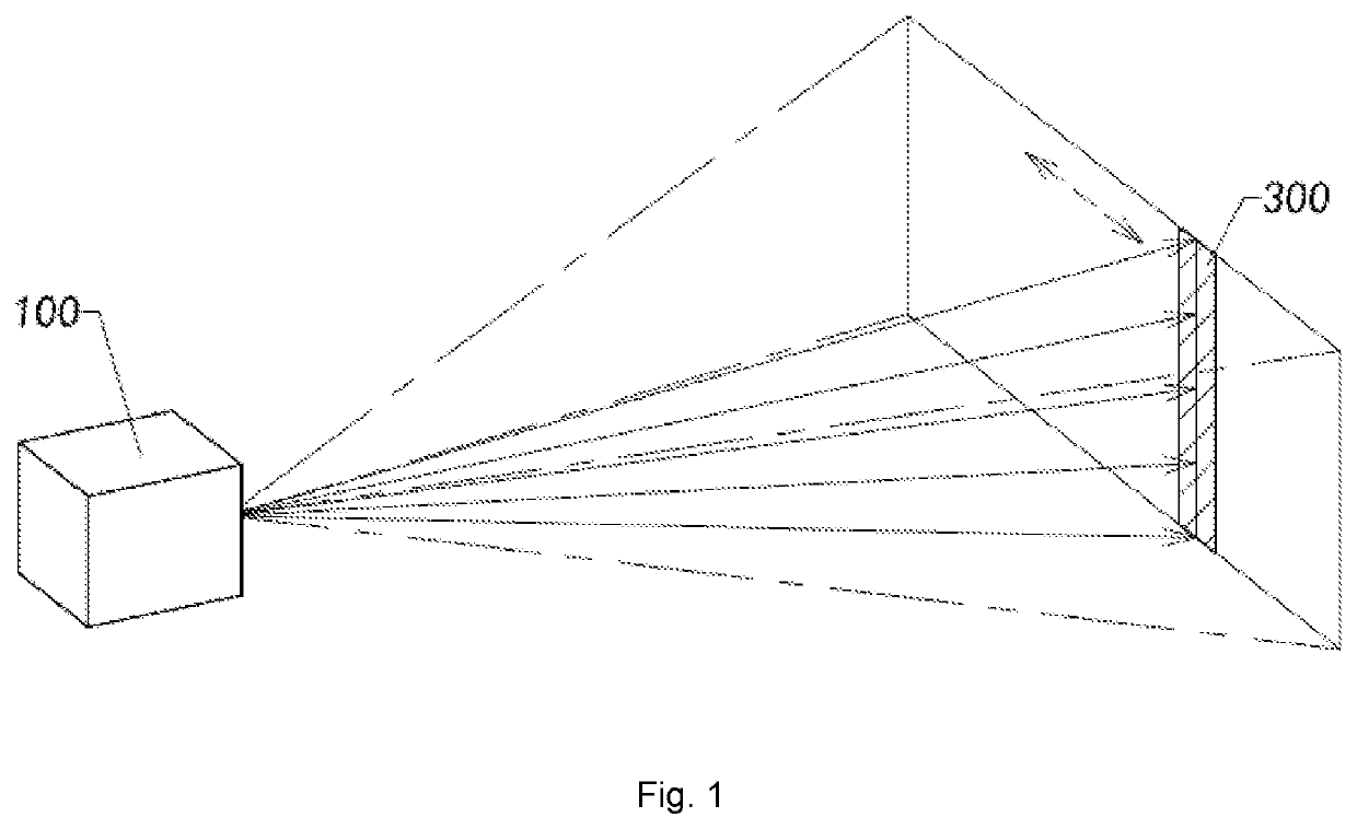
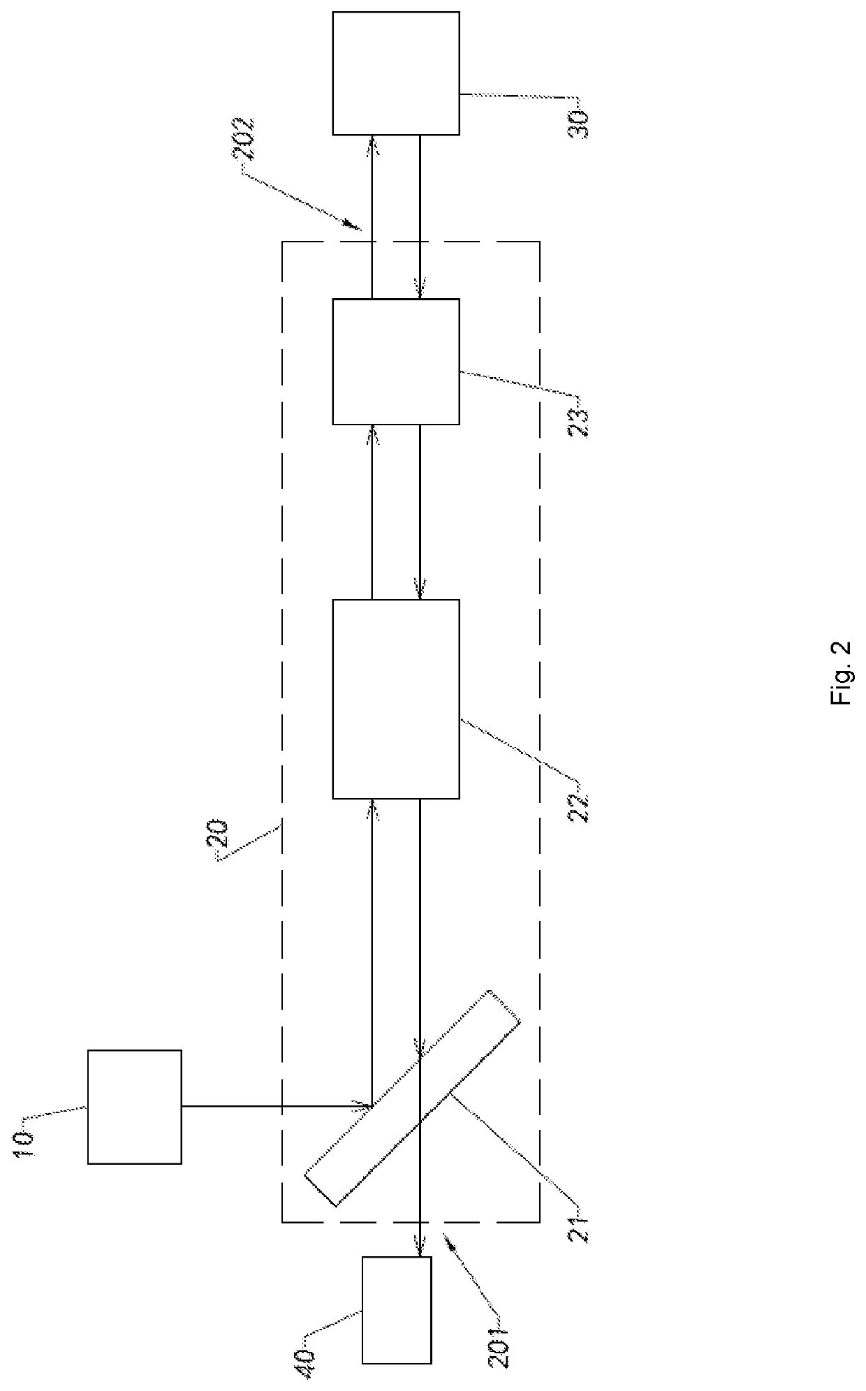
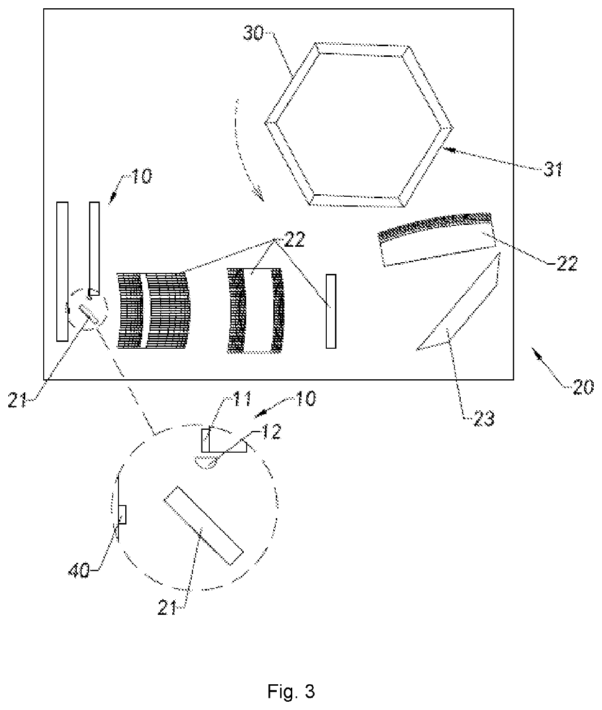

Image

  • Multi-point scanning lidar and detection method thereof
  • Multi-point scanning lidar and detection method thereof
  • Multi-point scanning lidar and detection method thereof

Examples


Embodiment Construction

[0047]The following description is presented to disclose the present disclosure to enable those skilled in the art to practice the present disclosure. Preferred embodiments in the following description are by way of example only, and other obvious modifications are conceivable to those skilled in the art. The basic principles of the present disclosure as defined in the following description may be applied to other implementations, modifications, improvements, equivalents, and other technical solutions without departing from the spirit and scope of the present disclosure.

[0048]It should be understood by those skilled in the art that in the disclosure of the present disclosure, the orientation or positional relationship indicated by the terms “longitudinal”, “transverse”, “upper”, “lower”, “front”, “back”, “left”, “right”, “vertical”, “horizontal”, “top”, “bottom”, “inside”, “outside”, etc. is based on the orientation or positional relationship shown in the drawings, which is merely f...


PUM


Abstract

A multi-point scanning lidar is disclosed, including at least one laser emitting end for emitting laser light, a scanning device, at least one light path transmission mechanism and a laser receiving end. The scanning device forms at least one light guide surface for transmitting the laser light to at least one target object. The light path transmission mechanism is arranged between the laser emitting end and the scanning device. The scanning device is arranged on a laser light path in such a manner that the light guide surface successively transmits the laser light to different parts of the target object. The laser light path is a path on which the laser light is transmitted to the target object via the light path transmission mechanism, wherein the laser receiving end receives and analyzes the laser light reflected by the target object.

Description

TECHNICAL FIELD[0001]The present disclosure relates to a lidar, and in particular to a multi-point scanning lidar and a detection method thereof.TECHNICAL BACKGROUND[0002]A lidar is a radar system that emits a laser beam to detect a target's location, speed and other characteristic quantities. The lidar system obtains the target's information such as distance and azimuth by receiving a laser signal emitted by the target. Current lidar systems include mechanical radar systems, hybrid solid-state lidars such as MEMS lidars, and solid-state radar systems such as 3D Flash solid-state radar systems.[0003]The existing mechanical radar systems need to drive the entire mechanical radar to rotate through the motor so as to realize the detection of the target object. However, the mechanical radar has a complex structure and heavy overall mass. Therefore, when the driving motor drives the mechanical radar to rotate, the problems such as slow speed and unstable speed will occur, which will furt...

Claims


Application Information

Patent Timeline
IPC IPC(8): G01S7/481G01S17/08G01S17/58
CPCG01S7/4817G01S17/58G01S17/08G01S7/4815G01S17/06G01S17/42
Inventor ZHANG, JUNMINGXU, CHAOYANG, JIACAO, YANTING
Owner NINGBO SUNNY AUTOMOTIVE OPTECH
Why Eureka
Try Eureka