Supercharge Your Innovation With Domain-Expert AI Agents!

Self-luminous display panel and self-luminous display panel manufacturing method

a technology of display panels and manufacturing methods, applied in the direction of electrical equipment, semiconductor devices, organic semiconductor devices, etc., can solve the problems of short circuit between anodes and cathodes, death points may occur, etc., and achieve high resistance.

Pending Publication Date: 2022-05-12
JOLED INC
View PDF0 Cites 0 Cited by
  • Summary
  • Abstract
  • Description
  • Claims
  • Application Information

AI Technical Summary

Benefits of technology

The present disclosure is about a self-luminous display panel with self-luminous elements arranged on a plane. Each self-luminous element has a pair of electrodes, functional layers (including a light emitting layer), and a sealing layer. The electrodes face each other, and one of them includes a metal layer. The functional layers are located between the electrodes, and the sealing layer covers them from a direction. The panel also includes a repaired self-luminous element with a foreign object among the functional layers. The electrode with the metal layer has a high resistance portion around the foreign object and a thickened portion at the outer edge of the metal layer. This invention provides a self-luminous display panel with improved design and performance.

Problems solved by technology

In such display devices, foreign matter may be mixed between the anode and the cathode of the organic EL element during manufacture, such that a dead point due to a short circuit between the anode and the cathode may occur.

Method used


Image

  • Self-luminous display panel and self-luminous display panel manufacturing method
  • Self-luminous display panel and self-luminous display panel manufacturing method
  • Self-luminous display panel and self-luminous display panel manufacturing method

Examples


embodiment 1

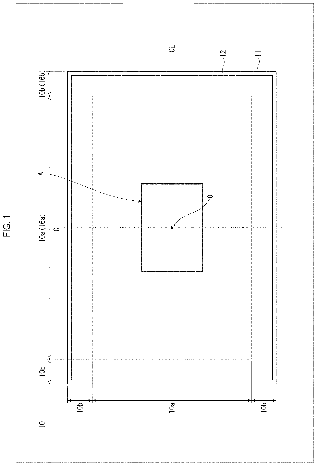
[0053]FIG. 1 is a plan view diagram of the display panel 10 according to The display panel 10 is an organic EL display panel that utilizes electroluminescence of organic material, in which organic EL elements are arranged in a matrix, for example on a top surface of a planarizing layer 12 on a substrate 11. As illustrated, the display panel 10, in plan view, is divided into a central area 10a corresponding to a defined range including a center O of a face of the substrate 11 and a peripheral area 10b around the central area 10a of the face of the substrate 11. Here, dimensions of the central area 10a in the X and Y directions of the substrate 11 may be, for example, from 50% to 90% of dimensions in the X and Y directions of the display panel 10. Further, in the substrate 11, dimensions of the peripheral area 10b in the X and Y dimensions may be, for example, from 5% to 25% of dimensions in the X and Y dimensions of the display panel 10, in an X or Y direction with respect to center...


PUM


Abstract

A self-luminous display panel 10 in which self-luminous elements 2 are arranged on a plane, wherein each of the self-luminous elements includes: a pair of electrodes 13, 20 disposed facing each other, an electrode of the pair of electrodes including a metal layer 20A; functional layers 15, 16, 17, 18, 19 including a light emitting layer 17, disposed between the pair of electrodes; and a sealing layer 21 that covers the pair of electrodes and the functional layers from a direction. The self-luminous elements include a repaired self-luminous element 2′. The repaired self-luminous element includes a foreign object FO among the functional layers. The electrode including the metal layer has a high resistance portion 201 surrounding, in plan view, an area containing the foreign object, and has a thickened portion 202 of the metal layer at an outer edge, in plan view, of the high resistance portion.

Description

[0001]This application claims priority to Japanese Patent Application No. 2020-186616 filed Nov. 9, 2020, the contents of which are hereby incorporated by reference in their entirety.BACKGROUNDTechnical Field[0002]The present disclosure relates to self-luminous display panels and self-luminous display panel manufacturing methods.Description of Related Art[0003]In recent years, as self-luminous displays using organic electroluminescence (EL) elements that utilize electroluminescence of organic material, organic EL panels in which organic EL elements are arranged in a matrix on a substrate are being put into practical use as electronic display devices. Each organic EL element has a basic structure in which various functional layers such as an electron transport layer and an organic light emitting layer containing an organic light emitting material are laminated between an anode and a cathode electrode pair. When driven, a voltage is applied between the electrodes, and holes injected f...

Claims


Application Information

Patent Timeline
IPC IPC(8): H01L51/52H01L51/56H01L27/32
CPCH01L51/524H01L2251/568H01L27/3218H01L51/56H10K59/353H10K59/1201H10K71/861H10K2102/351H10K59/87H10K50/841H10K71/00H10K50/822H10K50/828H10K50/826
Inventor MIYAJIMA, AKIOTSUCHIYA, MICHITOSHIKATO, HIROKINODA, MAKOTOOKUBO, MASAICHIAMATSUCHI, MARIO
Owner JOLED INC
Features
  • R&D
  • Intellectual Property
  • Life Sciences
  • Materials
  • Tech Scout
  • Unparalleled Data Quality
  • Higher Quality Content
  • 60% Fewer Hallucinations
Learn More