Cooling device for power battery system, power battery system and vehicle

a technology for cooling devices and power batteries, applied in the field of vehicles, can solve problems such as short circuit, damage to battery systems, and damage to battery systems, and achieve the effects of improving battery system performance, reducing temperature differences, and improving battery system safety

Pending Publication Date: 2022-05-12
WEBASTO AG
View PDF0 Cites 1 Cited by
  • Summary
  • Abstract
  • Description
  • Claims
  • Application Information

AI Technical Summary

Benefits of technology

[0015]In the cooling device of the present disclosure, the piping system is all disposed outside the battery system. Thus, battery cells or high-voltage devices inside the battery system would not be affected even if the coolant leaks at the piping system, which greatly improves safety of the battery system. Moreover, the liquid cooling plates of the liquid cooling plate assembly can be flexibly arranged in series and parallel connection, so that the flow distribution of the liquid cooling plates can be reasonably adjusted, which helps to reduce temperature differences between the battery cells, improve the performance of the battery system, and prolong the service life of the battery cells. In addition, the length and complexity of liquid cooling piping can be greatly reduced, which helps to reduce failure risk and cost.

Problems solved by technology

When the power battery system is operated at high power, charging and discharging processes of batteries produce a large amount of heat, causing heat buildup inside the batteries and causing degradation of battery performance.
However, there is a risk of coolant leakage in the liquid cooling system, which may cause the battery system to short circuit, catch fire or even explode.

Method used


Image

  • Cooling device for power battery system, power battery system and vehicle
  • Cooling device for power battery system, power battery system and vehicle
  • Cooling device for power battery system, power battery system and vehicle

Examples


Embodiment Construction

[0023]The implementation and application of the embodiments are discussed in detail below. It should be understood, however, that the specific embodiments of the present disclosure are only illustrative of specific ways to implement and apply the present disclosure without limiting the scope of the present disclosure. The representations of structural positions of various components, such as up, down, top, bottom, etc., in the description are not absolute, but rather relative. These orientation representations are appropriate when the various components are arranged as shown in the figures, but when the positions of the various components in the figures change, these orientation representations also change accordingly.

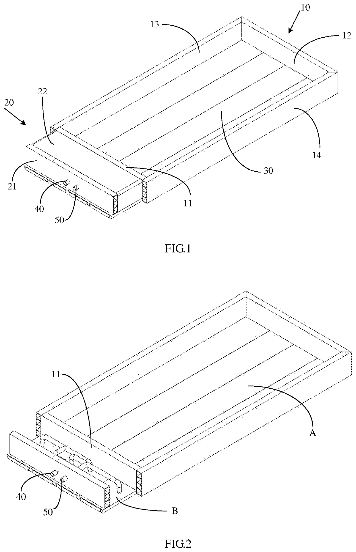
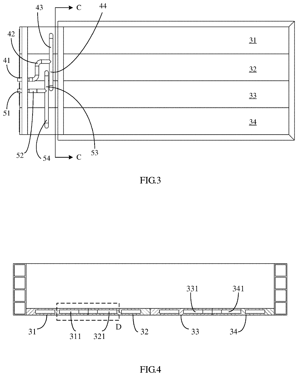
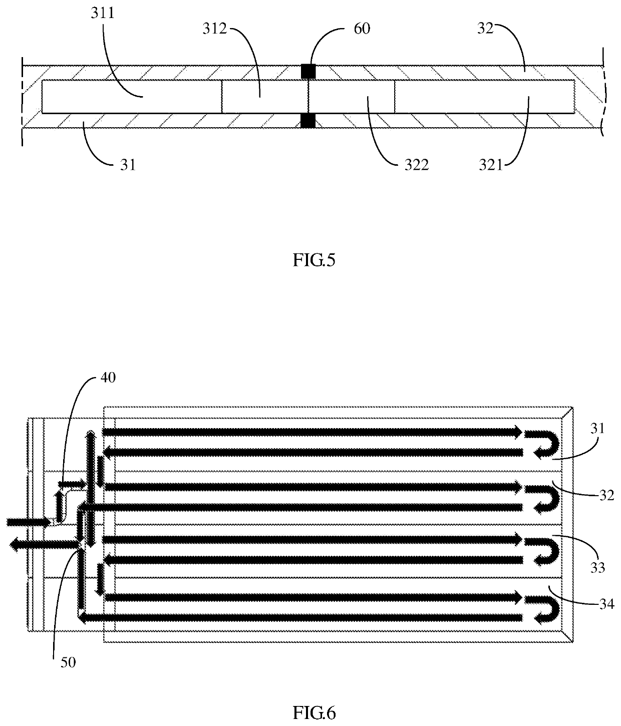
[0024]Generally, a power battery system for a vehicle includes a battery pack composed of a plurality of battery cells, and a cooling device is disposed at a bottom of the power battery system to help to quickly and evenly dissipate heat from the battery pack. To avoid...


PUM

PropertyMeasurementUnit
temperatureaaaaaaaaaa
energyaaaaaaaaaa
temperatureaaaaaaaaaa

Abstract

The present disclosure relates to a cooling device for a power battery system, a power battery system for a vehicle comprising the cooling device, and a vehicle. The cooling device is disposed at a bottom of the power battery system and includes a chamber defined by a casing. The chamber includes: a first region where a liquid cooling plate assembly is disposed; and a second region sealingly separated from the first region and accommodating a piping system for coolant communication. The liquid cooling plate assembly extends from a bottom of the first region to a bottom of the second region, and the piping system is in fluid communication with a flow passage of the liquid cooling plate assembly. In the cooling device of the present disclosure, the piping system is all disposed outside the battery system. Thus, battery cells or high-voltage devices inside the battery system would not be affected even if the coolant leaks at the piping system, which greatly improves safety of the battery system.

Description

CROSS-REFERENCE TO RELATED APPLICATIONS[0001]This application is a 35 U.S.0§ 371 National Stage Entry of International Application No. PCT / CN2019 / 127613, filed Dec. 23, 2019, which claims the priority benefit of China Patent Application Number 201822163284.2, filed Dec. 21, 2018, all of which are incorporated herein by reference in their entirety for all purposes.TECHNICAL FIELD[0002]The present disclosure generally relates to the field of vehicles, in particular to the field of power battery systems of new energy vehicles (electric vehicles, hybrid vehicles). More particularly, the present disclosure relates to a cooling device for a power battery system, a power battery system for a vehicle, and a vehicle having a power battery system.BACKGROUND[0003]Hybrid vehicles and pure electric vehicles typically require a highly efficient power battery system to provide energy. When the power battery system is operated at high power, charging and discharging processes of batteries produce a...

Claims


Application Information

Patent Timeline
Patent Type & Authority Applications(United States)
IPC IPC(8): H01M10/613H05K7/20H01M10/625H01M10/6554H01M10/6556H01M10/6568B60L50/64B60L58/26
CPCH01M10/613H05K7/20872H01M10/625H01M10/6554H01M2220/20H01M10/6568B60L50/64B60L58/26H01M10/6556H01M10/6567Y02E60/10Y02T10/70
Inventor ZHANG, QINGSHI, SHAOCHUNLI, QIUHUA
Owner WEBASTO AG
Why Eureka
Try Eureka