
Control apparatus for adjusting thermal stress

a control apparatus and thermal stress technology, applied in the direction of electric motor control, motor/generator/converter stopper, dynamo-electric converter control, etc., can solve the problems of unbalanced thermal stress in the svpwm scheme, unbalanced thermal stress concerns in the dpwm scheme,

Pending Publication Date: 2022-05-19
DELTA ELECTRONICS INC
View PDF2 Cites 0 Cited by
  • Summary
  • Abstract
  • Description
  • Claims
  • Application Information

AI Technical Summary

Benefits of technology

The patent describes a way to manage heat in multi-phase voltage source inverters, which helps reduce uneven stresses on switches. The technical effect of this invention is to improve the reliability and durability of multi-phase voltage source inverters.

Problems solved by technology

Further, within each phase, as the currents through the upper and lower switches are not necessarily the same, unbalanced thermal stresses are also present in the switches within each phase.
Even though DPWM schemes are substantively different from SVPWM schemes, the unbalanced thermal stress concerns in the SVPWM schemes are also present in the DPWM schemes.

Method used


Image

  • Control apparatus for adjusting thermal stress
  • Control apparatus for adjusting thermal stress
  • Control apparatus for adjusting thermal stress

Examples


Embodiment Construction

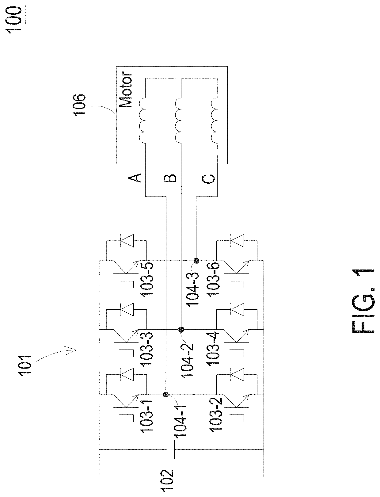
[0018]According to one embodiment of the present invention, in a multi-phase voltage source inverter operating at a near-zero output frequency, a control circuit implements a method (“the present control scheme”) that actively balances thermal stresses in the switches of the multi-phase voltage source inverter, based on a temperature difference between the upper and lower switches in the phase that supplies the highest output phase current. FIG. 4 is a block diagram of control circuit 400 that enables such a method in a three-phase voltage source inverter (e.g., three-phase voltage source inverter 100 of FIG. 1). In the three-phase voltage source inverter, control circuit 400 provides a zero-sequence adjustment to each of the duty cycle signals that drive the switches of the three-phase voltage source inverter. The zero-sequence adjustment is made at adder 404 to each duty cycle signal—i.e., each of duty cycles dA, dB and dC, for phases A, B and C, respectively. In FIG. 4, the pre-a...


PUM


Abstract

A method for balancing thermal stresses in semiconductor switching devices may include (a) monitoring temperatures of the semiconductor switching devices to provide a temperature difference between two of the switching devices; and (b) based on the temperature difference, providing a zero-sequence component to be used for adjusting conduction times of each of the semiconductor devices.

Description

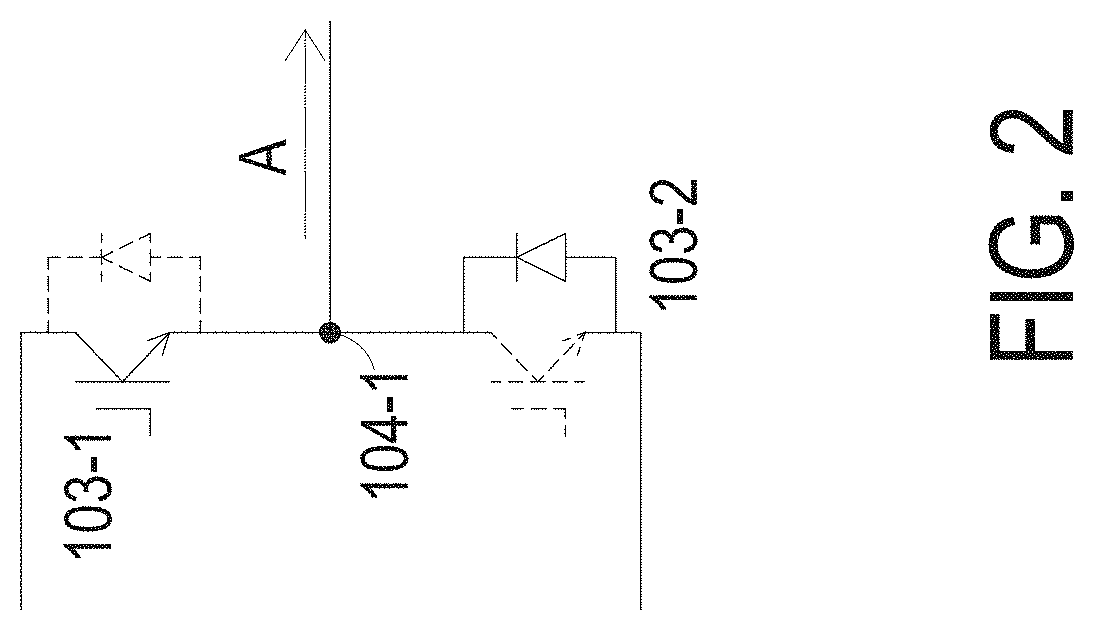
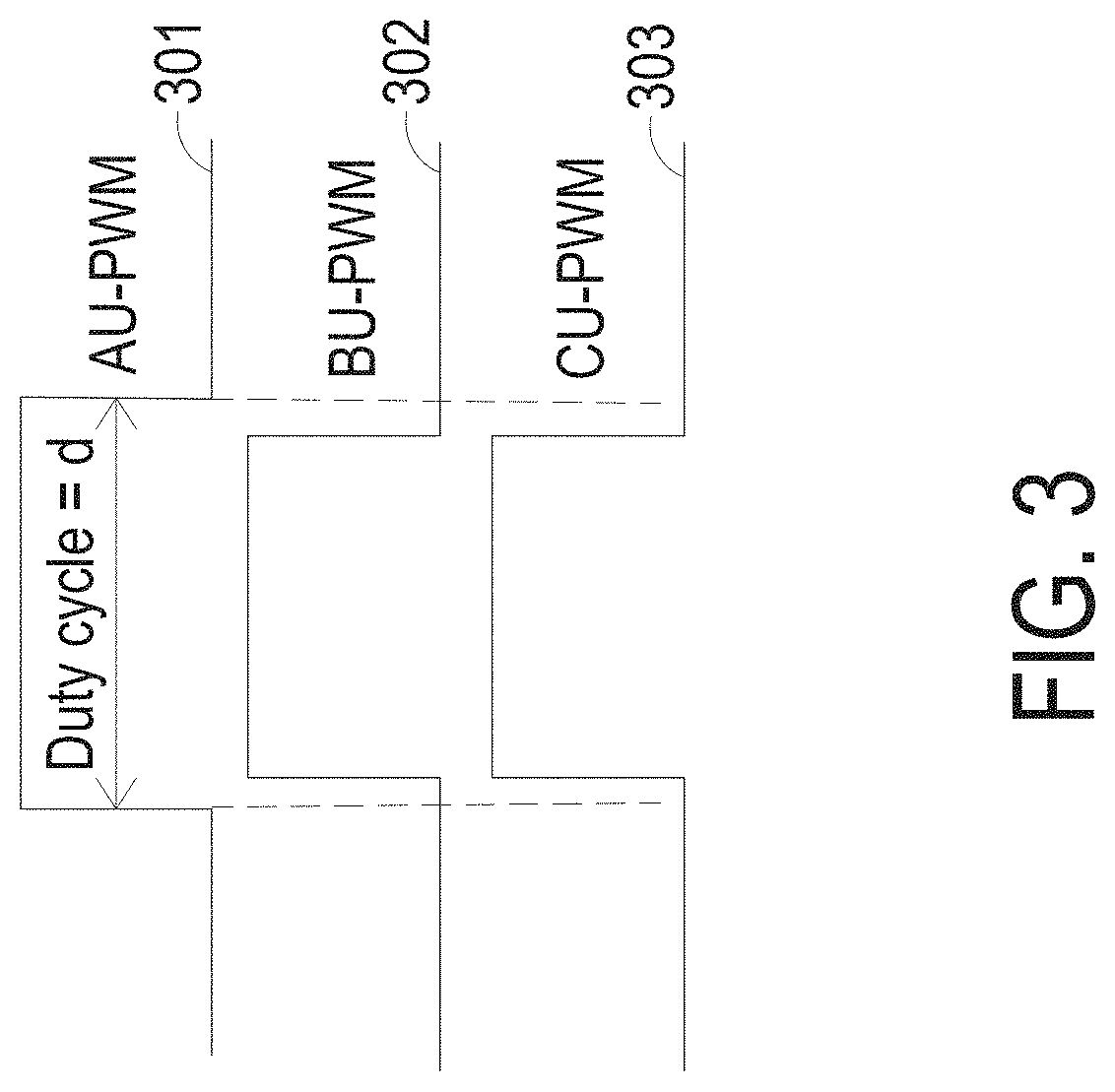
BACKGROUND OF THE INVENTION1. Field of the Invention[0001]The present invention relates to managing thermal stress in multi-phase voltage source inverter circuits. In particular, the present invention relates to reducing unbalanced stresses in switches of multi-phase voltage source inverter circuits.2. Discussion of the Related Art[0002]In an electric or a hybrid-electric vehicle, an electric motor drives the wheels. When the vehicle is stopped in an up-hill position, the electric motor maintains the vehicle in a stationary state (“hill-hold operation”) by providing a torque at zero or near-zero output frequency. Typically, a traction inverter drives the electric motor. FIG. 1 is a schematic diagram of three-phase voltage source inverter 100 driving electric motor 106; three-phase voltage source inverter 100 may be used as a traction inverter.[0003]As shown in FIG. 1, power module or stage 101 of three-phase voltage source inverter 100 includes DC-link capacitor 102—serving as a vol...

Claims


Application Information

Patent Timeline
IPC IPC(8): H02M1/32H02M1/084H02P3/02H02P3/18H02M7/797
CPCH02M1/32H02M1/0845H02M2001/327H02P3/18H02M7/797H02P3/025H02P27/085H02M7/5395H02M7/53871H02M1/327H02P29/68H02P21/00
Inventor ZHOU, YANSHAO, BAIMINGGUI, YINGYINGKLESYK, KRZYSZTOF S.
Owner DELTA ELECTRONICS INC
Learn More