Communication system, base station and communication terminal

a communication terminal and base station technology, applied in the field of communication systems, can solve problems such as collision risks, and achieve the effects of reducing the latency of communication between the base station device and increasing the power consumption of the communication terminal device, and saving the power consumption required for reception

Pending Publication Date: 2022-05-19
MITSUBISHI ELECTRIC CORP
View PDF3 Cites 0 Cited by
  • Summary
  • Abstract
  • Description
  • Claims
  • Application Information

AI Technical Summary

Benefits of technology

[0069]A communication system according to the present invention includes a base station device and at least one communication terminal device capable of radio communication with the base station device. The base station device notifies the communication terminal device of information on a next reception timing. The communication terminal device performs reception based on the information on the next reception timing that has been notified from the base station device. Since the communication terminal device can receive the information transmitted from the base station device with the notified reception timing, the power consumption required for the reception can be saved. Since retransmission can be promptly performed when the retransmission is necessary, the latency in the communication between the base station device and the communication terminal device can be reduced. Thus, increase in the power consumption of the communication terminal device, degradation in the communication quality, and reduction in the use efficiency of radio resources can be suppressed.

Problems solved by technology

The RACH involves a collision risk.

Method used


Image

  • Communication system, base station and communication terminal
  • Communication system, base station and communication terminal
  • Communication system, base station and communication terminal

Examples


first embodiment

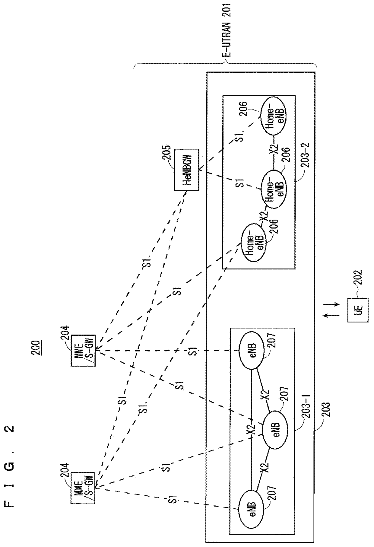
[0104]FIG. 2 is a block diagram showing an overall configuration of an LTE communication system 200, which is under discussion of 3GPP. FIG. 2 will be described. A radio access network is referred to as an evolved universal terrestrial radio access network (E-UTRAN) 201. A user equipment device (hereinafter, referred to as a “user equipment (UE)”) 202 that is a communication terminal device is capable of radio communication with a base station device (hereinafter, referred to as a “base station (E-UTRAN Node B: eNB)”) 203 and transmits and receives signals through radio communication.

[0105]Here, the “communication terminal device” covers not only a user equipment device such as a movable mobile phone terminal device, but also an unmovable device such as a sensor. In the following description, the “communication terminal device” may be simply referred to as a “communication terminal”.

[0106]The E-UTRAN is composed of one or a plurality of base stations 203, provided that a control pro...

second embodiment

[0277]The physical control channel to which uplink control information (UCI) is to be mapped is the PUCCH in the LTE. The PUCCH resources are set to each UE. For example, the scheduling request (SR) configuration such as the PUCCH resources for SR and the SR period is set to each UE (see 3GPP TS 36.211 V14.0.0 (hereinafter referred to as “Reference 3”) and 3GPP TS 36.213 V14.0.0 (hereinafter referred to as “Reference 4”). The RRC signaling is used in these settings (see 3GPP TS 36.331 V14.0.0 (hereinafter referred to as “Reference 5”)).

[0278]Multi-beamforming (MBF) requiring the beam sweeping is being studied in the NR. The MBF requiring the beam sweeping requires switching between beams to cover all the coverages. Since one subframe is solely used for transmitting and receiving one beam, the subframe cannot be used for transmitting and receiving the other beams. Thus, the conventional LTE setting method for configuring PUCCH resources for a plurality of UEs in one subframe has a pr...

second modification

of Second Embodiment

[0502]The first modification of the second embodiment discloses increasing the use efficiency of the radio resources through setting of the PUCCH resources for each UE to the UE. With the periodic setting of the PUCCH resources, however, communication needs to be always performed, with the timing, via a beam to which the PUCCH resources are set. In the presence of communication requiring the low latency via the other beams, a problem of a communication failure via a beam to which the PUCCH resources are set arises.

[0503]The second modification will disclose a method for solving such a problem.

[0504]The cell sets the PUCCH resources to the UE in a subframe identical to the subframe in which the DL resources are configured for the beams via which the UE communicates. The UE transmits the PUCCH in a subframe identical to the subframe in which the downlink signal for the serving beam is transmitted. In the NR, the self-contained subframe that consists of DL resources...


PUM


Abstract

Provided is a communication system capable of suppressing increase in the power consumption of a communication terminal device, degradation in the communication quality, and reduction in the use efficiency of radio resources. A base station device (gNB) notifies a communication terminal device (UE) of information on the next reception timing. The UE receives, for example, a downlink control signal in a subframe. The UE obtains, from the downlink control signal, information on a piece of user data in the subframe, and the information on the next reception timing. The UE transmits and receives the piece of user data to and from the gNB. The information on the next reception timing indicates a subframe as the next reception timing of the UE. The UE receives a downlink control signal in the subframe.

Description

CROSS-REFERENCE TO RELATED APPLICATIONS[0001]This application is a divisional of and claims the benefit of U.S. application Ser. No. 16 / 340,228, filed on Apr. 8, 2019, which is a National Stage Application of PCT / JP2017 / 046054, filed on Dec. 22, 2017, which claims the benefit of Japanese Patent Application No. 2016-249443, filed on Dec. 22, 2016.TECHNICAL FIELD[0002]The present invention relates to a communication system in which radio communication is performed between a communication terminal device such as a user equipment device and a base station device.BACKGROUND ART[0003]The 3rd generation partnership project (3GPP), the standard organization regarding the mobile communication system, is studying communication systems referred to as long term evolution (LTE) regarding radio sections and system architecture evolution (SAE) regarding the overall system configuration including a core network and a radio access network, which will be hereinafter collectively referred to as a netw...

Claims


Application Information

Patent Timeline
Patent Type & Authority Applications(United States)
IPC IPC(8): H04W72/12H04W16/28
CPCH04W72/1289H04W52/0209H04W16/28H04W84/042H04W72/046H04W72/23Y02D30/70
Inventor MOCHIZUKI, MITSURUSHIMODA, TADAHIROFUKUI, NORIYUKIKUSANO, MASAAKI
Owner MITSUBISHI ELECTRIC CORP
Why Eureka
Try Eureka