Venous Catheter Device Capable of Being Sealed

Pending Publication Date: 2022-06-02
ZHEJIANG BAIHUO HEALTH TECH CO LTD
0 Cites 0 Cited by

AI-Extracted Technical Summary

Problems solved by technology

During the indwelling period, flexible venous catheter eliminates the risk of puncture through the vein by the rigid front end of the needle tube; however, in case of no medical liquid infusion in such period, blood coagulation may easily occur in the venous catheter and at the opening due to slow local blood flow or blood stagnation.
In spite of measures including anticoagulants such as heparin for sealing the catheter and normal saline for flushing the catheter, thrombosis cannot be prevented in the venous catheter lumen, but may, if falling off, lead to life-threatening acute pulmona...

Benefits of technology

[0053]The beneficial effect of the invention is as follows:
[0054]1. The occluding wire can smoothly enter the venous catheter lumen under continuous guidance or intermittent but coaxial guidance.
[0055]2. During the indwelling period with no medical liquid infusion, the occluding wire fully occludes the top opening of the venous catheter, so that blood cannot enter the venous catheter lumen, eliminating the risk of thrombosis in the venous catheter lumen.
[0056]3. The cone-shaped head of the occluding wire can partia...

Abstract

An occludable venous catheter device includes a needle tube with a needle tube base; a venous catheter with a venous catheter base; a sealer, a front portion disposed inside a venous catheter lumen, a front end exposed out of a front-end opening; an occluding wire; an isolating element; a guide passage with a straight tube portion; a front-end opening connected to the venous catheter lumen; wherein the occluding wire is capable of entering the venous catheter lumen; the straight tube portion is coaxial with the venous catheter or is capable of moving in an externally-isolated manner to a position such that a central axis of the straight tube portion coincides with a central axis of the venous catheter; the occluding wire and the guide passage reach directly inside a chamber and are isolated from the outer environment.

Application Domain

Technology Topic

Image

  • Venous Catheter Device Capable of Being Sealed
  • Venous Catheter Device Capable of Being Sealed
  • Venous Catheter Device Capable of Being Sealed

Examples

  • Experimental program(13)

Example

Embodiment 1
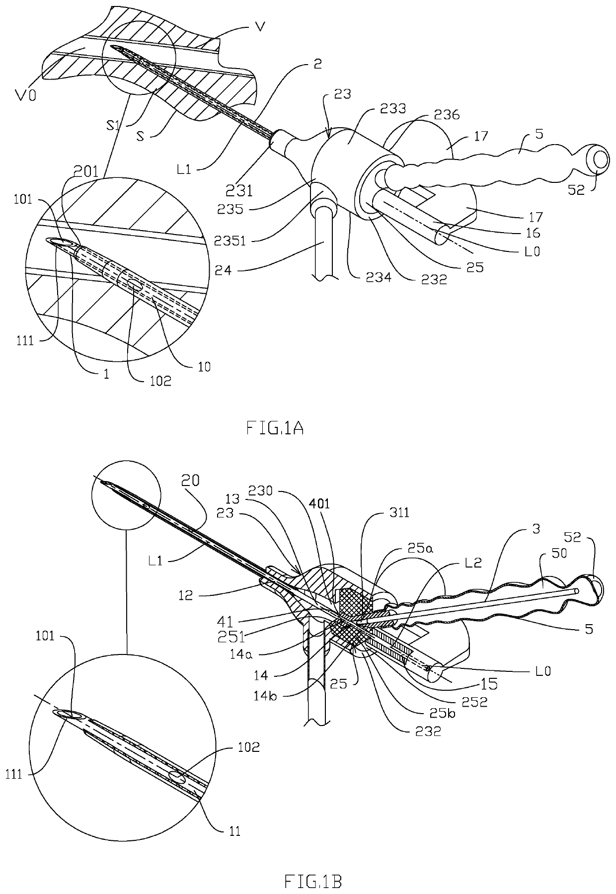
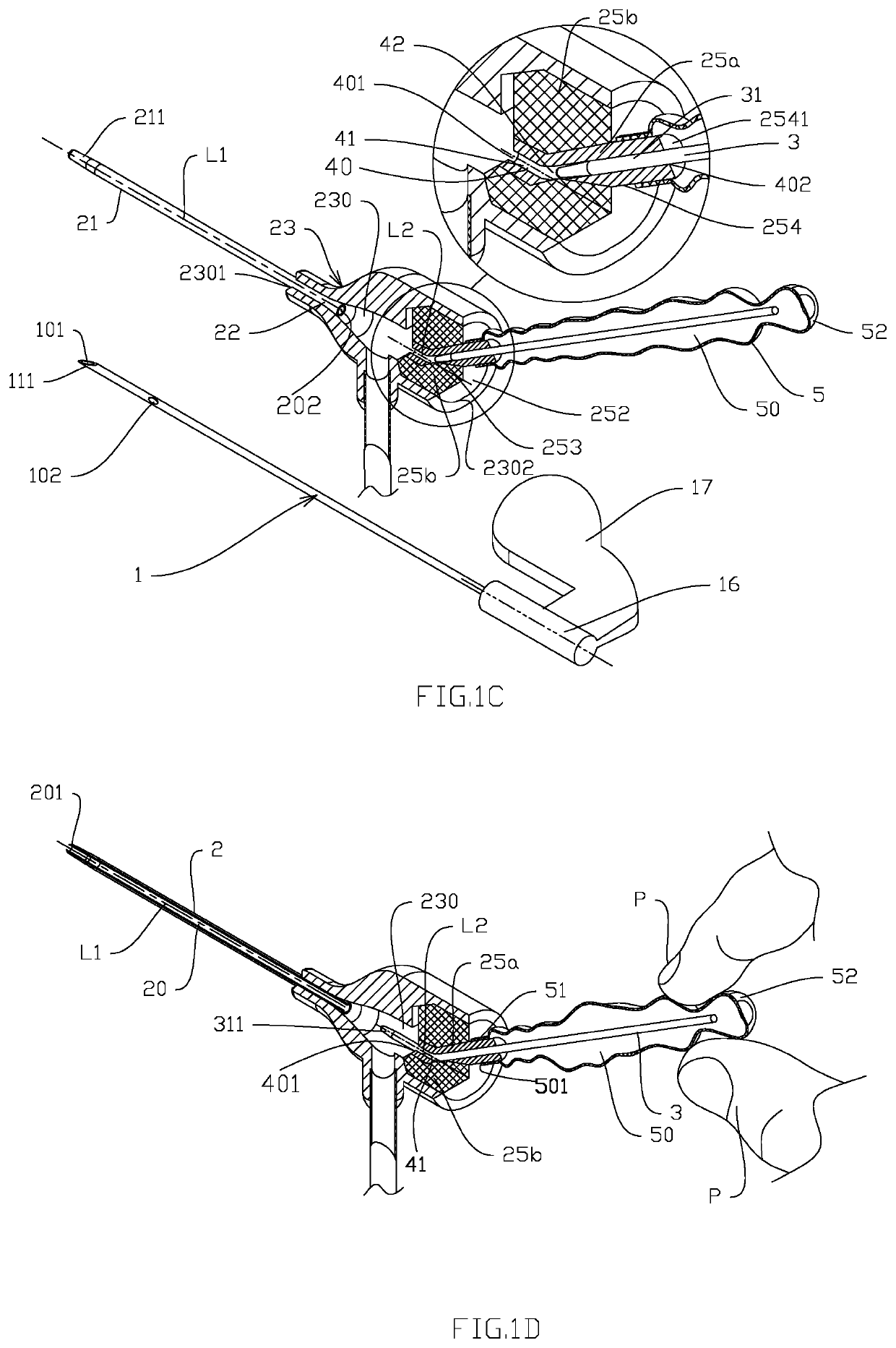
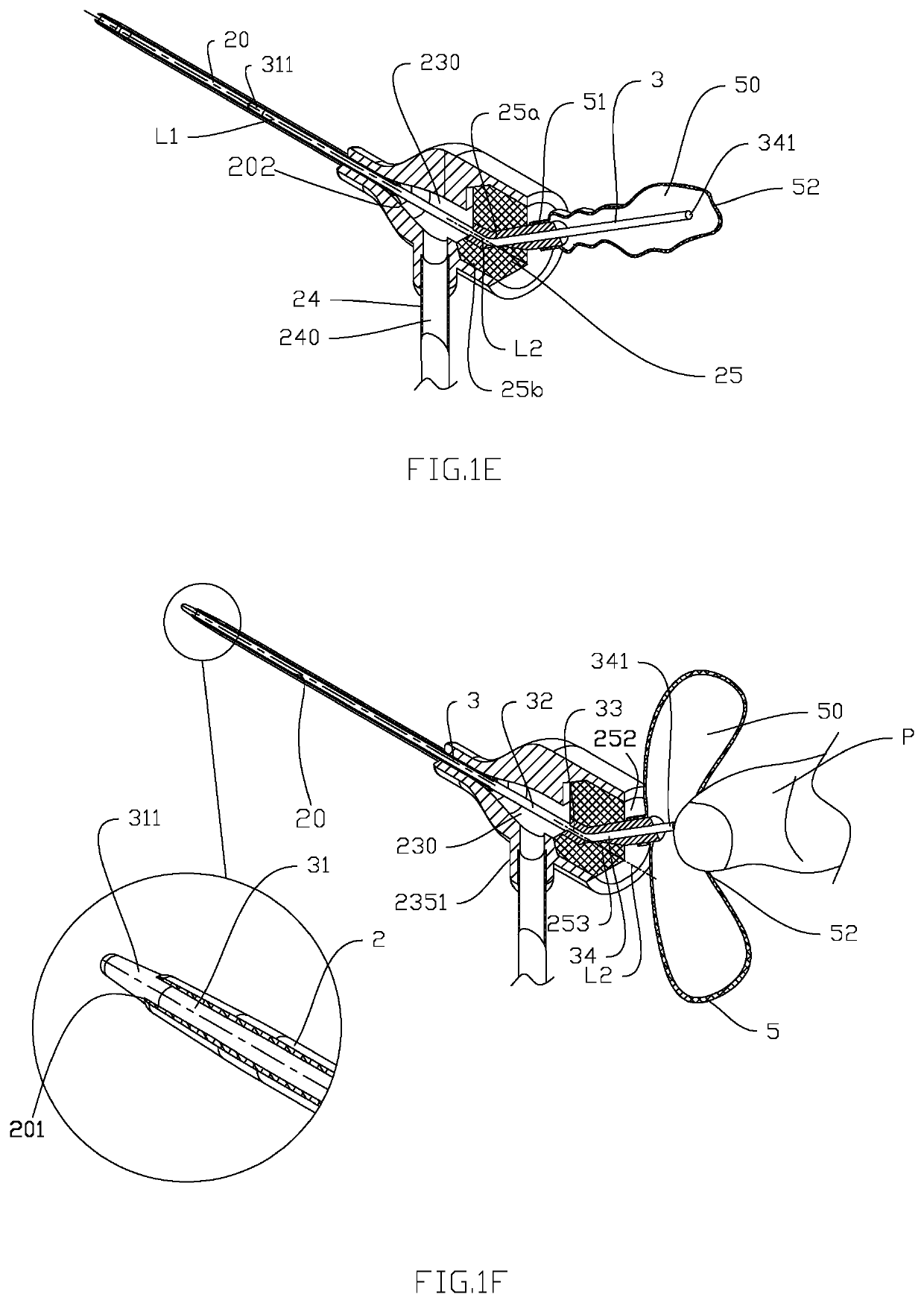
[0078]As shown in FIGS. 1A, 1B, 1C, 1D, 1E and 1F, the occludable venous catheter device of Embodiment 1 of the present invention comprises: a rigid needle tube 1 for puncturing skin S and venous wall V, a needle tube base 16, a venous catheter 2, a venous catheter base 23, a sealer 25, an occluding wire 3, a occluding wire guide passage 40 and an isolating element 5; the needle tube 1 is hollow inside and has a needle tube lumen 10, a bottom portion 15, a front portion 11 and a sharp front end 111, the front portion 11 of the needle tube 1 is located inside the venous catheter lumen 20, the sharp front end 111 is exposed from a front-end opening 201 of the venous catheter 2 during puncture, the needle tube lumen 10 has an opening 101 at the front end 111 of the needle tube 1, and the front portion 11 of the needle tube 1 has a side opening 102 near the front end 111 of the needle tube 1; a connecting portion 12 of the needle tube 1 is located in the area of a front end 231 of the venous catheter base 23, a middle portion 13 of the needle tube 1 is located in a chamber 230 of the venous catheter base 23, a passing portion 14 of the needle tube 1 is located in the sealer 25, a bottom portion 15 of the needle tube 1 is fixed in the needle tube base 16, and the needle tube base 16 is connected with a needle tube base handle 17; the relatively flexible hollow venous catheter 2 can be made of PU, FEP and other materials, and comprises a front portion 21 and a rear portion 22. The front portion 21 of the venous catheter 2 has a tapered front end 211. The medical liquid flows into the vein V through the front-end opening 201 of the venous catheter 2 via the venous catheter lumen 20, and the venous catheter lumen 20 is connected with the chamber 230 of the venous catheter base 23 through a rear-end opening 202; between a front end 231 and a rear end 232 of the venous catheter base 23 is an upper surface 233, a lower surface 234, a left side surface 235 and a right side surface 236. The chamber 230 has a smaller front-end opening 2301 in the front end 231 and a larger rear-end opening 2302 in the rear end 232. The front-end opening 2301 is sleeved with the hollow rear portion 22 of the venous catheter 2, and the rear-end opening 2302 of the venous catheter base 23 is filled with the sealer 25; the left side surface 235 of the venous catheter base 23 has a hollow infusion collateral 2351 which is connected with an infusion connecting pipe 24, and the chamber 230 of the venous catheter base 23 is communicated with an infusion connecting pipe lumen 240; a front surface 251 of the sealer 25 is adjacent to the chamber 230 of the venous catheter base 23, and a rear end surface 252 faces outward. The sealer 25 comprises a hard portion 25a and an elastic portion 25b. The hard portion 25a can be made of resin PC, as, ABS, etc., the elastic portion 25b can be made of elastic materials such as silicone rubber, polyurethane, etc., and the elastic portion 25b can close and seal the area it passes through after the needle tube 1 is extracted; the hard portion 25a of the sealer 25 has the occluding wire guide passage 40, a straight tube portion 41 is at the front of the guide passage 40, the rear portion 42 is obliquely connected with the straight tube portion 41, and the guide passage 40 has a front-end opening 401 and a rear-end opening 402; the occluding wire 3 can enter the guide passage 40 from the rear-end opening 402 of the guide passage 40; outside the occluding wire 3 is a deformable isolating element 5 in a saccular shape with thin wall, which can be made of flexible film materials such as silicone rubber, polyurethane, polyethylene, EVA, PET, etc. A front end 51 of the isolating element 5 has an opening 501, and a rear end 52 is a blind end. The front end 51 of the isolating element 5 is sleeved in a sealed manner with a cylindrical or flat external convex portion 254 of the hard portion 25a of the sealer 25, which can be connected by bonding, hot melting, ultrasonic welding and other methods in a sealed manner. Part of the rear portion 42 of the guide passage 40 is located in the convex portion 254, and the rear-end opening 402 of the guide passage 40 is located on a rear surface 2541 of the convex portion 254; the parts of the occluding wire 3 that may be in direct contact with the chamber 230 of the venous catheter base 23 and/or in communicated with fluid are all located in a chamber 50 of the isolating element 5. In this embodiment, an end 341 of the occluding wire 3 is completely located in the chamber 50 of the isolating element 5.
[0079]As shown in FIG. 1A, the needle tube 1 and the venous catheter 2 puncture the skin surface S, a subcutaneous tissue Si and the venous wall V, the sharp front end 111 of the needle tube 1 enters a venous lumen VO, and venous blood flows into needle tube lumen 10 and is observed by the operator through transparent venous catheter 2 at the side opening 102 at the front end 111 of the needle tube 1, so as to confirm the success of puncture.
[0080]In the initial state as shown in FIG. 1B, a central axis L0 of the needle tube 1, a central axis L2 of the straight tube portion 41 of the guide passage 40, and a central axis L1 of the venous catheter are collinear. A portion 14a of the passing portion 14 of the needle tube 1 is located in the straight tube portion 41 of the guide passage 40 of the hard portion 25a of the sealer 25, and another portion 14b of the passing portion 14 of the needle tube 1 passes through the elastic portion 25b of the sealer 25; at this time, the front-end opening 401 of the guide passage 40 is occupied by the needle passing portion 14a, and the occluding wire 3 cannot enter the chamber 230 of the venous catheter base 23.
[0081]As shown in FIG. 1C, after venipuncture is completed, the needle tube 1 is removed, and the elastic portion 25b of the sealer 25 closes a linear area 253 through which the needle tube 1 passes and isolates it from the outside due to the rebound deformation of the material. At this time, the front-end opening 401 of the guide passage 40 is connected with the chamber 230 of the venous catheter base 23; as shown in FIG. 1D, because the straight tube portion 41 of the guide passage 40 is coaxial with the venous catheter 2, that is, the central axis L2 of the straight tube portion 41 of the guide passage 40 is collinear with the central axis L1 of the venous catheter 2, the occluding wire 3 enters into the chamber 230 of the venous catheter base 23 under the coaxial guidance of the straight tube portion 41 of the guide passage 40; as shown in FIG. 1E, the occluding wire 3 enters the venous catheter lumen 20 through the rear-end opening 202 of the venous catheter 2; as shown in FIG. 1F, the occluding wire 3 finally blocks the front-end opening 201 of the venous catheter 2, and the isolating element 5 deforms, and compresses and accumulates towards the direction of rear surface 252 of the sealer 25; this coaxial straight entry design makes it easier for the occluding wire 3 to enter the venous catheter lumen 20, with far better effect than the method of oblique entry with different axes.
[0082]As shown in FIG. 1F, in the occluded state, the part of the occluding wire 3 located in the venous catheter lumen 20 is defined as a front section 31 having a blind end 311, the part located in the chamber 230 of the venous catheter base 23 is defined as a middle section 32, the part located in the straight tube portion 41 of the guide passage 40 is defined as a rear section 33, and the rest is defined as a tail section 34. The end 341 of the tail section 34 is located in the chamber 50 of the isolating element 5, the blind end 311 of the front section 31 of the occluding wire 3 is tapered and extends from the front-end opening 201 of the venous catheter 2, which minimize the risk of blood vortex during occlusion; the blind end 311 of the occluding wire 3 and the front-end opening 201 of the venous catheter 2 contact with each other as blood barrier, that is, blood cannot pass through the clearance between the venous catheter 2 and the occluding wire 3, which can be interference fit with each other or conformal fit with each other.
[0083]In this embodiment, the occluding wire 3 is a solid wire, which can be made of resin materials such as PU, PA, PET and PDFE by extrusion or molding, or metal materials such as nickel-titanium alloy; when in use, the operator's finger P presses and pinches the flexible membrane-shaped isolating element 5 to fix the occluding wire 3 in its chamber 50, and drives the occluding wire 3 forward or backward. Specifically, the operator can press and pinch the bottom end 52 of the isolating element 5 and the end 341 of the occluding wire tail section 34 in the isolating element 5.

Example

Embodiment 2
[0084]FIGS. 2A, 2B, 2C, 2D, 2E, 2F, 2G, 2H and 21 show a venous catheter device of Embodiment 2, the biggest difference from Embodiment 1 is that, in the initial state, the central axis L2 of the straight tube portion 41 of the guide passage 40 is not coaxial but parallel to the central axis L1 of the venous catheter 2. FIG. 2A shows that the needle tube base 16 is located below the isolating element 5, and the upper surface 233 of the venous catheter base 23 has an arched window 2331, a part of the hard portion 25a of the sealer 25 is exposed in the arched window 2331. The hard portion 25a of the sealer 25 is connected with a rotation handle 255, which is connected with the hard portion 25a of the sealer 25 through a neck 2551; the section view of FIG. 2B shows that the blind end 311 of the front section of the occluding wire 3 is located in the guide passage 40 and adjacent to the rear-end opening 402. The front-end opening 401 of the guide passage 40 faces a convex 2303 of the chamber 230 of the venous catheter base 23, and the occluding wire 3 cannot enter the venous catheter lumen 20; the hard portion 25a and the elastic portion 25b of the sealer 25 are interlaced with each other by means of secondary molding, bonding and interference fit, and they can move synchronously; when there is no interference of the needle tube 1 in the venous catheter lumen 20, the rotation handle 255 rotates from the left side of the arched window 2331 to the right side, which can make the sealer 25 rotate and move with the centerline L3 of the venous catheter base 23 as the axis; FIG. 2C shows that the needle tube 1 is pulled away from the sealer 25, the linear area 253 is closed and isolated from the outer environment, a concave 256 of the needle tube base 16 on the sealer 25 is empty, and the linear area 253 is still located on the extended line of the central axis L1 of the venous catheter 2; as shown in FIG. 2D, the operator's finger P acts on the handle 255 on the hard portion 25a of the sealer 25, and drives the handle 255 to rotate from the left side of the arched window 2331 to the right side. When the neck 2551 cannot move, it means that the handle 255 has rotated in place. At this time, the central axis L2 of the straight tube-shaped guide passage 40 is collinear with the central axis L1 of the venous catheter 2. As shown in FIG. 2E, the finger P applies force on the isolating element 5 to drive the blind end 311 of the front section of the occluding wire to move along the direction of the arrow on the central axis L1 of the venous catheter 2; FIG. 2F shows that the blind end 311 of the front section 31 of the occluding wire 3 is tapered and extends from the front-end opening 201 of the venous catheter, thus occluding the venous catheter 2, and the whole isolating element 5 is compressed axially and deformed to both sides; in order to clearly show the principle of achieving coaxial relationship by rotating and moving, the sectional view of FIG. 2G shows that in the initial state, the needle tube 1 is located in the venous catheter lumen 20, the central axis L2 of the straight tube-shaped guide passage 40 is not coaxial but parallel to the central axis L1 of the venous catheter 2, and the rotation axis L3 is located between them; the sectional view of FIG. 2H shows that the needle tube 1 is removed from the sealer 25, and there is no interference factor of rotation and movement at this time; the sectional view of FIG. 2I shows the state after rotation in place. The central axis L2 of the straight tube-shaped guide passage 40 and the central axis L1 of the venous catheter 2 are in a collinear position. In this embodiment, the guide passage 40 is straight in the whole process, without bending and tilting parts. The whole rotation is carried out on the premise of isolating from the external environment, and there is no risk of microorganisms or foreign matters entering the chamber 230 of the venous catheter base 23; when intravenous infusion is needed, the occluding wire 3 only needs to be pulled out from the venous catheter lumen 20 so that it does not occlude the rear-end opening 202 of the venous catheter.

Example

Embodiment 3
[0085]FIGS. 3A, 3B, 3C and 3D show a venous catheter device of Embodiment 3, the biggest difference, compared to method of making the central axis L2 of the straight tube-shaped guide passage 40 on the sealer 25 colinear with the central axis L1 of the venous catheter 2 by rotation in an externally-isolated manner in embodiment 2 is that, the guide passage 40 is formed by an independent hollow passage element 4, and the collinearity is realized by translation rather than rotation of external in an externally-isolated manner.
[0086]As shown in the section view FIG. 3A, there is a tubular convex 2332 on the upper surface 233 of the venous catheter base 23, the tubular convex 2332 is sleeved with the passage element 4, the passage element 4 has an extended section 43 extending from the outer surface 2333 of the tubular convex 2332 of the venous catheter base 23, the inner surface of the front end 51 of the isolating element 5 is connected with the outer surface of the tubular convex 2332 in a sealed manner, and the extended section 43 of the passage element 4 is located in the chamber 50 of the isolating element 5. The passage element 4 can be driven by an external force applied to the extended section 43 to perform translation relative to the tubular convex 2332. The front section of the bending hollow part of the passage element 4 is the straight tube portion 41 of the guide passage 40, the rear section 42 is obliquely connected with the front section 41, and the front section 31 of the occluding wire 3 enters into the rear section 42 of the guide passage 40, the central axis L2 of the straight tube portion 41 of the guide passage 40 is parallel to the central axis L1 of the venous catheter 2, but the sealer 25 can be completely made of elastic material without rotation; in the initial state, the passage element 4 cannot move downward due to the obstruction of the needle tube 1.
[0087]When in use, after successful venipuncture, the needle tube 1 starts to retreat from the sealer 25, and as shown in FIG. 3B, after the needle tube 1 is pulled out, it will no longer hinder the descending of the passage element 4.
[0088]As shown in FIG. 3C, the finger P pinches the area near the front end 51 of the isolating part to make the flexible isolating element 5 contact the extended section 43 of the passage element 4 and push it downward with force. The passage element 4 descends until the central axis L2 of the straight tube portion 41 is coaxial with the central axis L1 of the venous catheter 2. At this time, the front end of the straight tube portion 41 of the passage element 4 contacts the inner wall of the venous catheter base 23 and cannot continue to move.
[0089]As shown in FIG. 3D, the front section 31 of the occluding wire 3 extends from the front-end opening 401 of the guide passage 40 and advances along the central axis L1 of the venous catheter 2 into the venous catheter lumen 20. Due to reliable isolation, microorganisms and other foreign matters in the external environment will not be brought into the chamber 230 of the venous catheter base 23, that is, they will not enter into the venous lumen VO; of course, the tubular convex 2332 on the venous catheter base 23 can also be disposed on the left side surface 235 or the right side surface 236 of the venous catheter base 23.

PUM

no PUM

Description & Claims & Application Information

We can also present the details of the Description, Claims and Application information to help users get a comprehensive understanding of the technical details of the patent, such as background art, summary of invention, brief description of drawings, description of embodiments, and other original content. On the other hand, users can also determine the specific scope of protection of the technology through the list of claims; as well as understand the changes in the life cycle of the technology with the presentation of the patent timeline. Login to view more.

Similar technology patents

Classification and recommendation of technical efficacy words

Why Eureka
Try Eureka