
Guidewire with internal pressure sensor

a technology of pressure sensor and guidewire, which is applied in the field of advance in pressure guidewire technology, can solve the problems of fracture and other failure modes, high cost, and thin and achieve the effects of reducing the cost of materials, preventing a change in material properties, and reducing the thickness of pressure guidewires

Pending Publication Date: 2022-06-09
OPSENS
View PDF0 Cites 1 Cited by
  • Summary
  • Abstract
  • Description
  • Claims
  • Application Information

AI Technical Summary

Benefits of technology

The patent text describes the need for stronger and more robust pressure guidewires to prevent failure modes and enhance kink resistance. The guidewires should have junctions that preserve delicate structures that measure pressure, as well as thicker walls in the intermediate section to provide flexibility and a stepped lumen profile. The method for forming the guidewire involves coupling the proximal and distal bodies together and applying heat to enhance ductility. The pressure sensor is integrated into the shaft tube assembly and the tip assembly includes a core wire with a distal end having a rounded shape and a coil positioned over it to prevent material property changes.

Problems solved by technology

Pressure guidewires are very thin and yet contain sophisticated devices in complex assemblies.
The assembly process and requirements of use can lead to fracture and other failure modes.
In some examples, the sensor that makes pressure measurements includes a micro-electromechanical systems (MEMS) devices which are very small and also very delicate.

Method used


Image

  • Guidewire with internal pressure sensor
  • Guidewire with internal pressure sensor
  • Guidewire with internal pressure sensor

Examples


Embodiment Construction

[0042]This application is directed to improved design and construction techniques for pressure guidewires. Such techniques provide robust connections between separate structures enhancing and fracture resistance. Such techniques provide connections that protect delicate structures from damage caused by stress concentration resulting from material degradation within localized heat affected zone(s), such as can arise during welding and other heat generating manufacturing steps.

I. Overview of Pressure Wire Systems and their Use

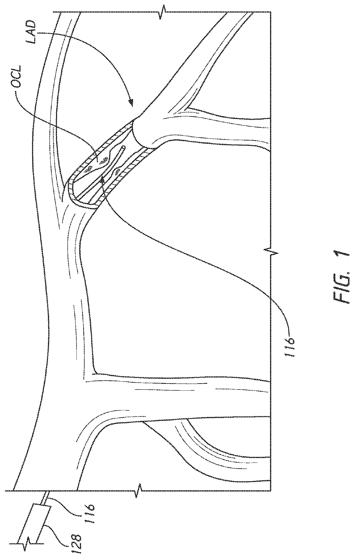
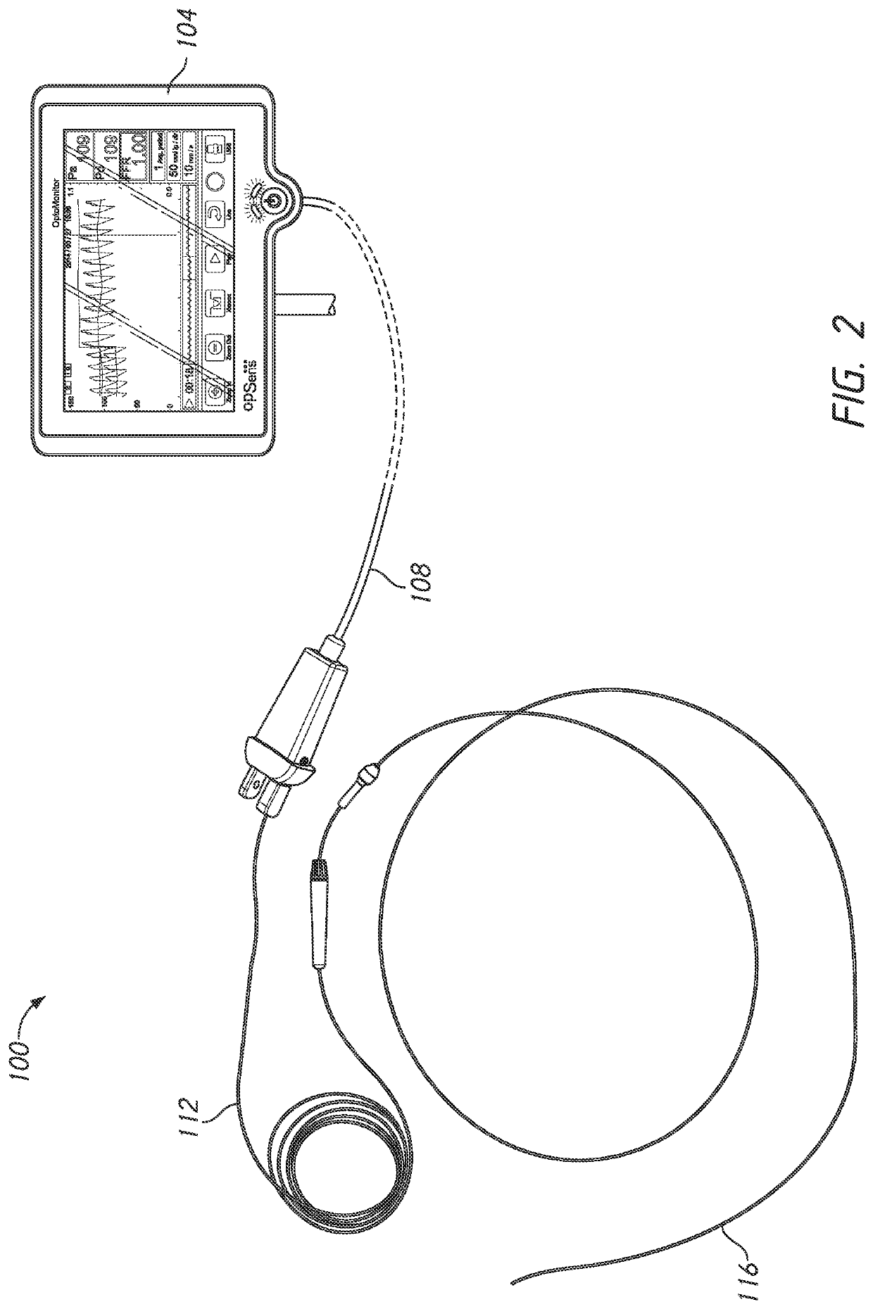
[0043]FIGS. 1 and 2 illustrate a lesion diagnostic system 100 and the use thereof in the vasculature of a patient. FIG. 1 illustrates the left side coronary vasculature with a pressure guidewire 116 disposed in a proximal portion of a left anterior descending artery (LAD). The pressure guidewire 116 is positioned in the left anterior descending artery LAD with a distal portion thereof distal to an occlusion OCL. The pressure guidewire 116 is positioned through a ...


PUM


Abstract

A pressure guidewire is provided that has a proximal end and a distal end. The pressure guidewire has a proximal section a sensor housing section, and an intermediate section. The proximal section extends from the proximal end of the pressure guidewire to a distal end of the proximal section. The sensor housing section is disposed adjacent to the distal end of the pressure guidewire. The intermediate section disposed between the proximal section and the sensor housing section. The intermediate section has a proximal end separate from the proximal section. The proximal end can be coupled to the distal end of the proximal section. The pressure guidewire has a tubular body positioned within the intermediate section. A pressure sensor is positioned in the sensor housing section

Description

INCORPORATION BY REFERENCE TO ANY PRIORITY APPLICATIONS[0001]Any and all applications for which a foreign or domestic priority claim is identified in the Application Data Sheet as filed with the present application are hereby incorporated by reference under 37 C.F.R. § 1.57.BACKGROUNDField[0002]This application is directed to advancements in pressure guidewire technology.Description of the Related Art[0003]Guidewires are known for delivering catheters to many vascular locations in the body. Access to remote and tortuous vasculature is facilitated by a combination of mechanical properties such as flexibility, pushability and torqueability.[0004]Coronary catheters can track over simple coronary guidewires to coronary vasculature and can be used to position treatment devices dilatation balloons and stents. Some coronary guidewires are also able to measure blood pressure in the segment of the coronary vasculature. Upon measurement of blood pressure, a treatment diagnosis can be used to ...

Claims


Application Information

Patent Timeline
Patent Type & Authority Applications(United States)
IPC IPC(8): A61B5/0215A61M25/09A61M25/00
CPCA61B5/0215A61M25/09A61M2205/0244A61M2025/09175A61M2025/0002A61M25/0043
Inventor LALANCETTE, SEBASTIENBELLEVILLE, CLAUDELAFLEUR, PHILIPPEMERCIER, JEAN-SEBASTIEN
Owner OPSENS
Learn More