Heating System with Low Leakage Current

Pending Publication Date: 2022-06-16
DEBIOTECH SA
View PDF0 Cites 0 Cited by
  • Summary
  • Abstract
  • Description
  • Claims
  • Application Information

AI Technical Summary

Benefits of technology

[0013]One of the aims described in this document is to overcome the aforemention

Problems solved by technology

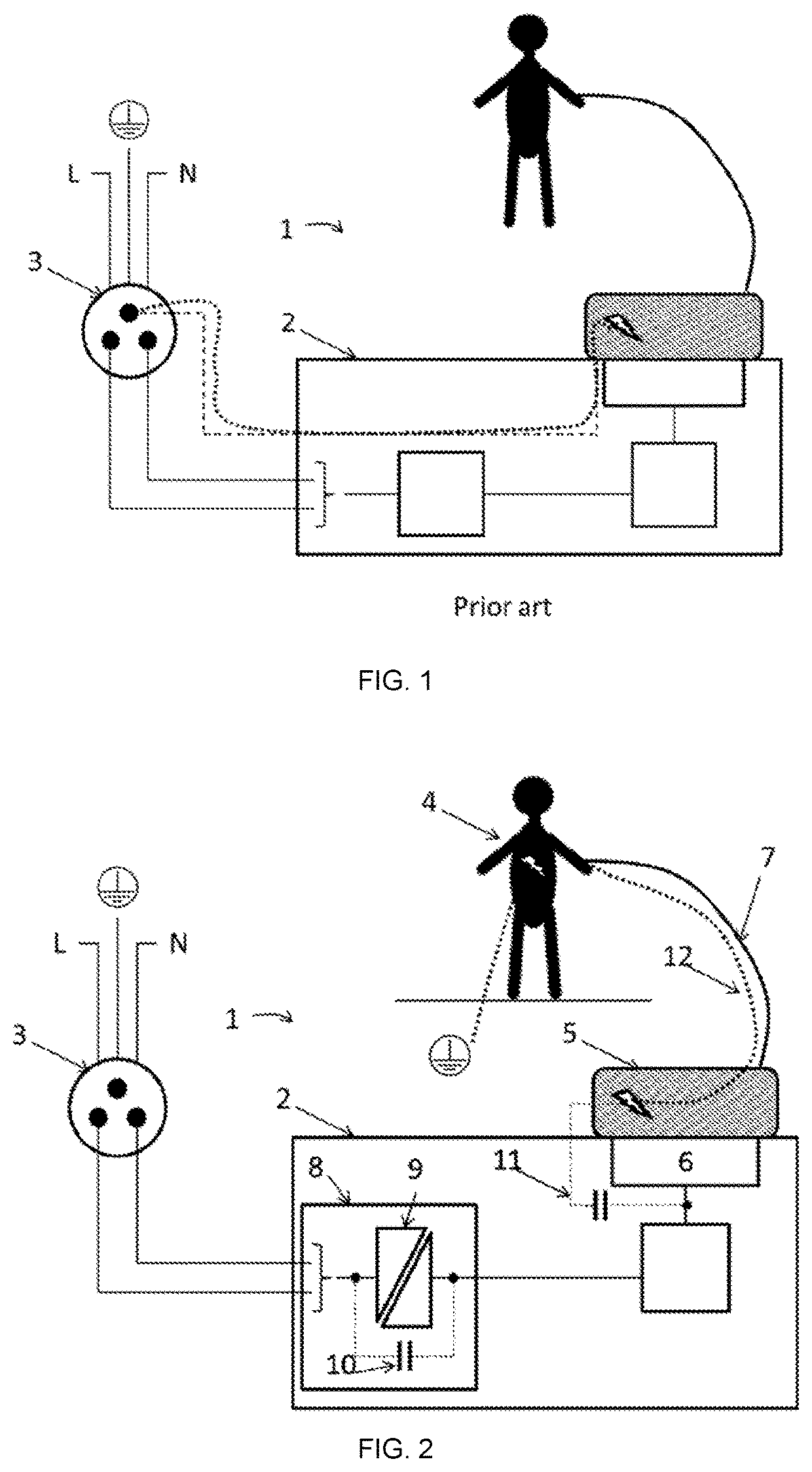
Depending on the power required to power the appliance, it is not economically and/or technically possible to find a commercially available power supply that itself meets the requirements of the CF leakage current level.
This type of appliance drastically limits the freedom of these patients, since it is difficult to contemplate (even simply impossible) calling upon a certified electrician in a hotel bedroom, in the homes of friends, etc.
Furthermore, in general, in the case whereby the medical appliance is intended for domestic use, it is preferable to start from the principle that the leakage currents will not be reduced by grounding on the secondary side of the power supply or the applied parts, since this grounding can be defective or inexistent.
However, these heating devices can require a powerful power supply (as previously discussed) generating significant leakage currents that propagate through the fluid paths reaching the applied parts in contact with the patient.
However, even if a power supply is perfectly designed, a certain amount of parasitic capacitance (10) exist

Method used


Image

  • Heating System with Low Leakage Current
  • Heating System with Low Leakage Current
  • Heating System with Low Leakage Current

Examples


example of an embodiment

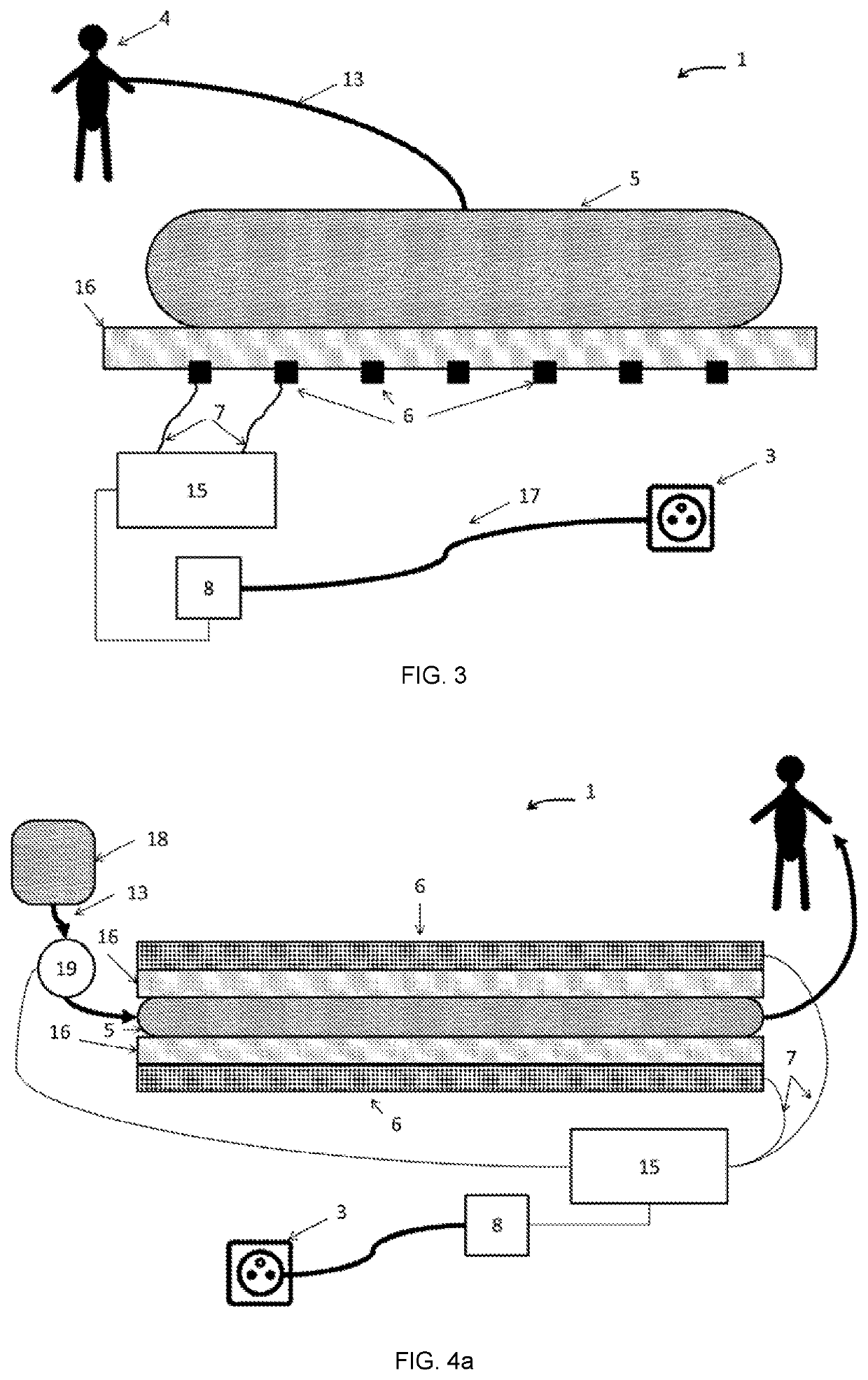
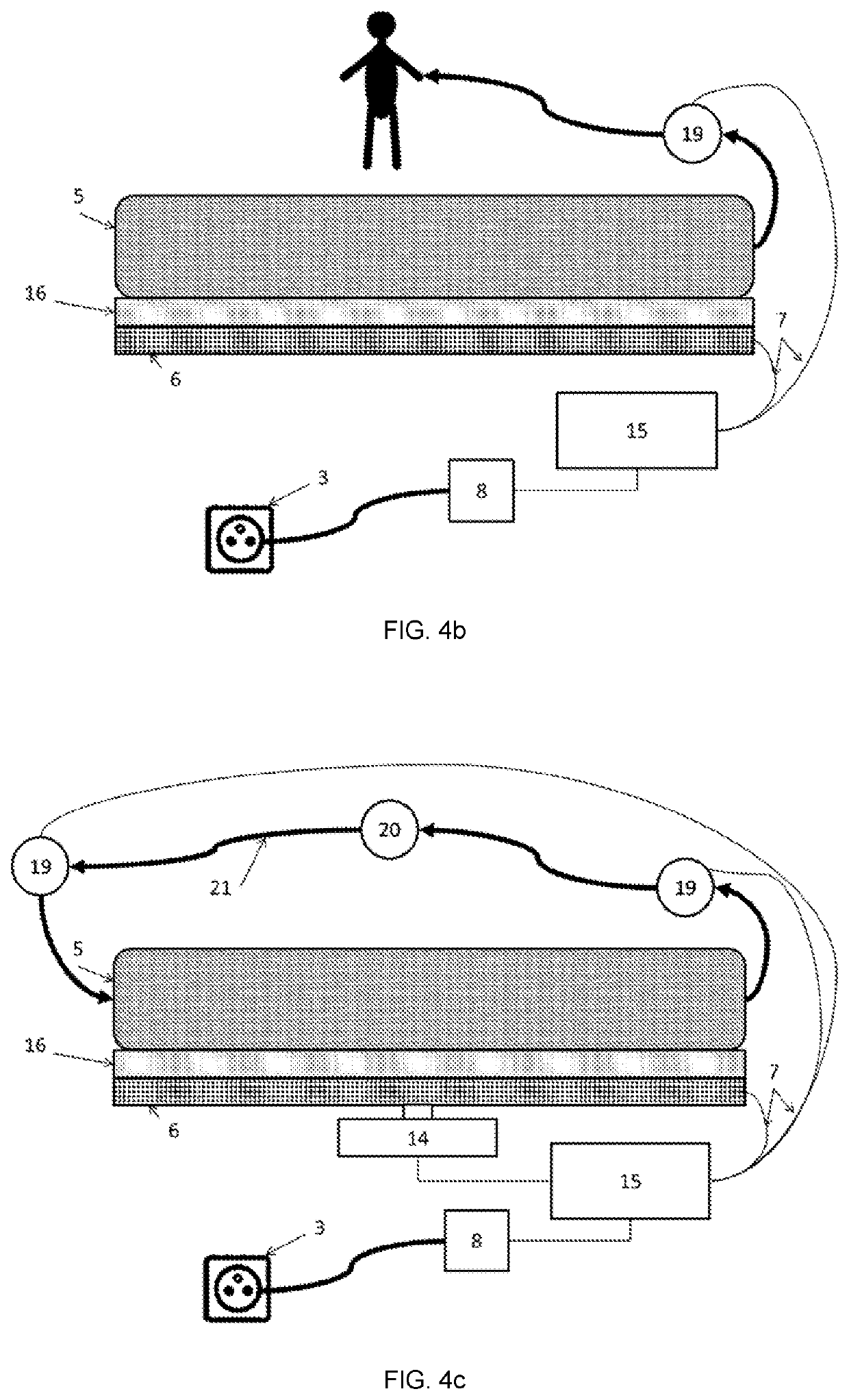
[0221]According to some embodiments, as disclosed in FIG. 8, the heating system (101) comprises a heat source (108) and an interface comprising an insulating layer (109) configured to limit the electrical coupling (in particular capacitive coupling) between the heat source (108) and the fluid to be heated (not shown herein), in order to limit the leakage current of the system to less than 10 μA.

[0222]Preferably, the system comprises one or more stacked layer(s). Furthermore, the interface can comprise at least one of the following additional layers:[0223]a first heat transfer layer (110); and / or[0224]a second heat transfer layer (112).

[0225]The first heat transfer layer (110) can be configured to come into contact with the receptacle of fluid to be heated (not shown herein). This first heat transfer layer (110) can comprise an upper surface and a lower surface. The upper surface can be intended to be in contact with the receptacle of fluid to be heated. The lower surface can be inte...


PUM


Abstract

A heating system for medical fluid that comprises a receptacle for medical fluid to be heated, a heating element powered by a power supply inducing a leakage current (to ground) ranging between 100 and 10 μA. The heating system further comprises an interface device (for example, an electrical insulation and thermal interface device) disposed between the heating element and the medical fluid contained in the receptacle, allowing the heating system to induce a leakage current in the medical fluid that is less than 10 μA at the applied part.

Description

FIELD OF THE INVENTION[0001]The present invention generally relates to a medical system adapted to heat a fluid, for example, a dialysis machine comprising a heating system. More specifically, the invention can relate to a heating system, an arrangement or a method for heating a fluid.PRIOR ART[0002]Some medical appliances require an extremely low patient leakage current level. This is particularly the case for applications where the applied part is directly in contact with or very close to the heart of the patient (“direct cardiac application”). The applied part in this case must meet a “cardiac floating (CF)” level, which is equivalent to a patient leakage current that is less than or equal to 10 μA during normal operation.[0003]Depending on the power required to power the appliance, it is not economically and / or technically possible to find a commercially available power supply that itself meets the requirements of the CF leakage current level. Indeed, for example, the commercial...

Claims


Application Information

Patent Timeline
IPC IPC(8): A61M1/16A61M1/28A61M5/44
CPCA61M1/1664A61M1/1629A61M2205/36A61M5/44A61M1/28A61M1/166A61M1/3623
Inventor LEVEN, SÉVERIN
Owner DEBIOTECH SA
Why Eureka
Try Eureka