Aircraft landing gear assembly

a technology for landing gear and aircraft, which is applied in the direction of landing gear, aircraft components, undercarriages, etc., can solve the problems of resonance effect and large dynamic airframe loading, and achieve the effect of effective lever stopping, convenient maintenance and improved stability

Pending Publication Date: 2022-06-16
AIRBUS OPERATIONS LTD
View PDF1 Cites 0 Cited by
  • Summary
  • Abstract
  • Description
  • Claims
  • Application Information

AI Technical Summary

Benefits of technology

[0007]This enables the fore and aft landing gear levers to be arranged such that the rear lever is angled further downwards than the fore lever. Hence, fore tyres are set slightly higher and the rear tyres set slightly lower than level. I.e. the rear tyres are closer to the ground. This means that, in use, even if an aircraft is approaching landing in a flat configuration (i.e. the rotational mounting axis, which is substantially parallel to a longitudinal axis of the aircraft, being substantially horizontal), the rear wheel would touch down on the runway ground prior to the fore wheel. This means that the landing gear, through the linkage assemblies, can provide a smoother, softer touchdown for crew and passengers, even in such a flat configuration. This is because only the rear wheel can touchdown at a certain time; the fore wheel touches down later (i.e. after the rear wheel has touched the ground). This reduces the dynamic loads experienced by the airframe, which enables the airframe to be lighter. This is especially important as flat landings are often performed at higher descent rates than tail down landings (and so have the potential to be more uncomfortable and to cause greater dynamic airframe loading). The aft wheel touching down first causes the aft wheel to “spin-up” before the fore wheel, as the “spin-up” of the wheels is caused by the impulse of the tyre contacting the ground. On a conventional landing gear, the vibrations associated with the “spin-up” of the fore and aft wheels are felt at the same time, which can cause additional forces due to resonance effects. These additional forces coincide with the vertical load exerted on the airframe as the aircraft touches down. Thus, airframes are made structurally stronger to withstand these vibrations. Having the vibrations associated with the “spin-up” of the aft wheel and the fore wheel occur at different times can reduce any resonance effects that result from the vibrations from the “spin-up” of the wheels, and thus reduces the force exerted on the airframe. Thus, the rear wheel touching down before the fore wheel, allows for structural savings in the weight of the airframe.
[0025]Preferably, the fore linkage assembly and rear linkage assembly are linked so that the load sharing between the fore and aft wheels is balanced. This allows load to be shared between the fore lever and the aft lever. This therefore allows loads to be shared between wheels substantially equally, e.g. if there are two fore wheels and one rear wheel, each wheel on the landing gear assembly will experience substantially the same load. This has the advantage of resulting in less wear on tyres, and makes the landing gear assembly easier to manage and maintain. An additional advantage is that such a load sharing mechanism will result in less damage to runways. For example, the fore linkage assembly and rear linkage assembly may be linked by a balance beam. The balance beam may allow the load to be shared between the wheels substantially equally.

Problems solved by technology

This is especially important as flat landings are often performed at higher descent rates than tail down landings (and so have the potential to be more uncomfortable and to cause greater dynamic airframe loading).
On a conventional landing gear, the vibrations associated with the “spin-up” of the fore and aft wheels are felt at the same time, which can cause additional forces due to resonance effects.
However, if the bogie is nominally almost flat in flight, it is possible to get spurious or flickering indications of “weight on wheels” during taxiing as the bogie slightly pitches up & down from ground undulations.

Method used


Image

  • Aircraft landing gear assembly
  • Aircraft landing gear assembly
  • Aircraft landing gear assembly

Examples


first embodiment

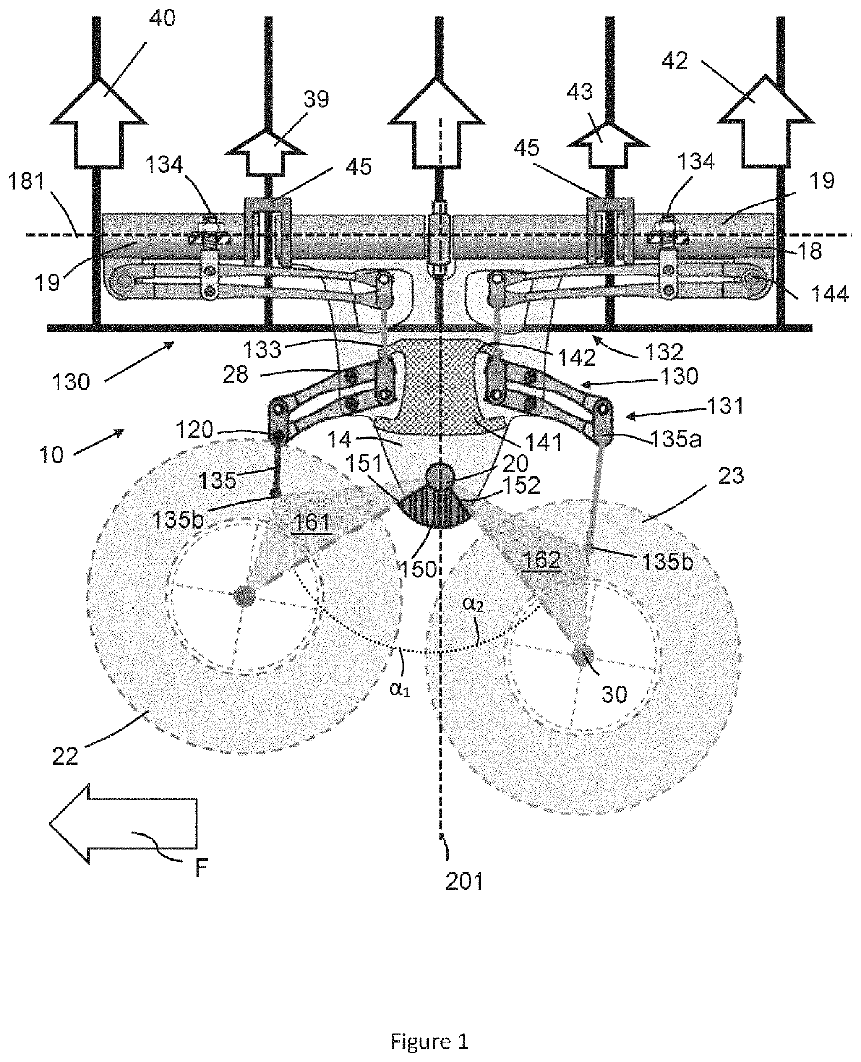
[0048]FIG. 1 shows schematically an aircraft landing gear assembly 10 according to the invention, suitable for use on an aircraft (such as that shown on FIG. 7). The fore direction is shown in FIG. 1 with the arrow labelled F. The aircraft landing gear assembly comprises a bracket and spring assembly arrangement for transmitting ground loads, which has various potential design advantages as compared to prior landing gear assemblies which transmit the majority of ground loads utilising a single elongate landing gear leg with an integrated shock absorber (referred to in the art often as an oleo landing gear design). The bracket acts as the main fitting for the aircraft landing gear assembly.

[0049]The landing gear assembly 10 of FIG. 1 includes a bracket 14 extending from a hinge portion 18 to a first mounting point 20 for mounting at least two wheels 22, 23 via one or more pivoting levers 16. The hinge portion 18 allows for mounting of the bracket 14 for rotation relative to a landing...

second embodiment

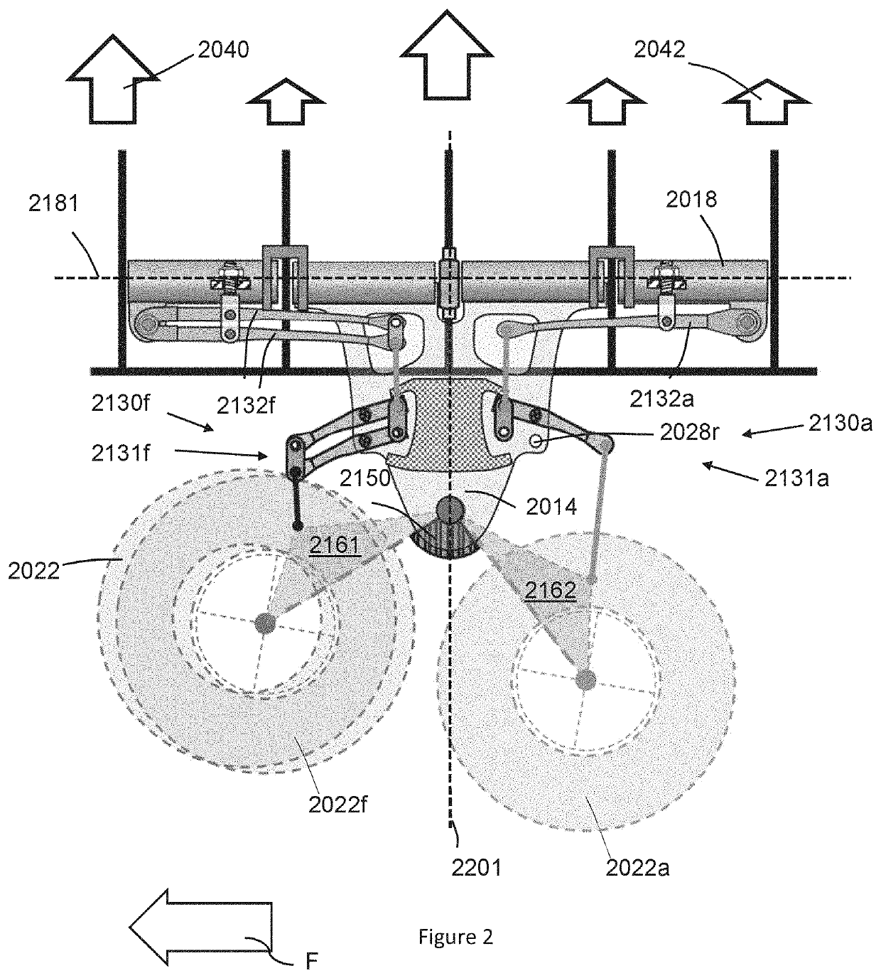
[0072]FIG. 2 shows a landing gear assembly similar to that shown in FIG. 1. Like reference numerals are used for like parts, but adding 2000 to the numbers used in FIG. 1. The main differences between the two embodiments will now be described. The landing gear 2010 has two levers 2016 which between them carry three wheels 2022. In this embodiment, the fore wheel 2022f is mounted such that it is arranged centrally (in the span-wise direction) relative to the bracket. The centre plane of the wheel 2022f—such a plane having the wheel axis as its normal—is substantially coplanar with the corresponding centre plane of the bracket (or at least, the bracket 2014 and wheel 2022f are so arranged that the main load bearing structure of the bracket extends to either side of the centre plane of the wheel). The central mounting of the fore wheels 2022f and 2022 is readily achieved as a result of the spaced apart parallel plates that form the bracket 2014. The fore wheels 2022 in front of the af...

third embodiment

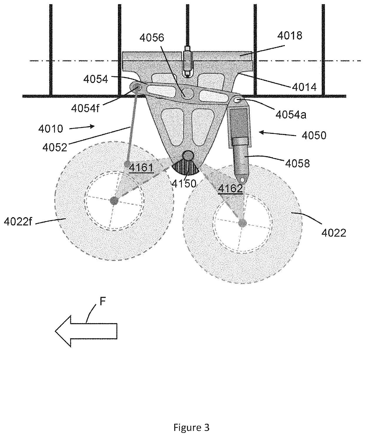
[0075]FIG. 3 shows a two-wheel landing gear assembly similar to that shown in FIGS. 1 and 2 Like reference numerals are used for like parts, but adding 4000 to the numbers used in FIG. 1. The main differences between the previous embodiments will now be described. The bracket 4014 is shorter in the fore-aft direction at its upper end, in that the hinge portion is shorter. The loads transmitted into the aircraft body are therefore more concentrated (in the fore-aft direction). In a variation of this embodiment, the hinge portion is the same length and the bracket 4014 has a substantially identical shape as in FIG. 1. The bracket 4014 also uses a shock absorber and linkage system 4050 instead of one or more spring assemblies. As such the structure providing the stops that interact with the spring system as shown in FIG. 1 (which stop structure may be modular—and separately removable—in any case) is not present in the embodiment of FIG. 3. The shock absorber and linkage system 4050 co...


PUM


Abstract

An aircraft landing gear assembly is disclosed including a landing gear bracket, a fore lever receiving a fore aircraft wheel, an aft lever receiving a rear aircraft wheel, the fore and aft levers being independently moveable, wherein the bracket further comprises a fore lever stop to prevent downwards movement of the fore lever past a lowest rotational position with respect to the bracket at a first angle α1 forward from the notional bracket axis, and a rear lever stop to prevent downwards movement of the rear lever past a lowest rotational position at a second angle α2 behind from the notional bracket axis, wherein the first angle is greater than the second angle. An aircraft and a method of landing an aircraft are also disclosed.

Description

BACKGROUND OF THE INVENTION[0001]The present disclosure relates to an aircraft landing gear assembly.[0002]The present invention concerns aircraft landing gear assemblies. More particularly, but not exclusively, this invention concerns an aircraft landing gear assembly, wherein the aircraft landing gear assembly comprises: i) a landing gear bracket comprising: a hinge portion for rotationally mounting the bracket relative to a landing gear bay, the hinge portion defining an axis of rotational mounting of the bracket, a first mounting point, the shortest distance from the axis of rotational mounting to the first mounting point defining a notional bracket axis, ii) a fore lever having a first end which is rotatably mounted to the bracket at the first mounting point and a second end for receiving a fore aircraft wheel, iii) an aft lever having a first end which is rotatably mounted to the bracket at the first mounting point and a second end for receiving a rear aircraft wheel, the fore...

Claims


Application Information

Patent Timeline
Patent Type & Authority Applications(United States)
IPC IPC(8): B64C25/50B64C25/36
CPCB64C25/50B64C25/36B64C25/12B64C25/60B64C25/62B64C25/10B64C25/34
Inventor THOMPSON, ROBERT IAN
Owner AIRBUS OPERATIONS LTD
Why Eureka
Try Eureka