Formation method for liquid rubber composite nodes with tubular flow channel

a liquid rubber composite and flow channel technology, applied in mechanical equipment, vibration suppression adjustments, shock absorbers, etc., can solve the problems of high maintenance cost, difficult to realize the above characteristics of the existing liquid rubber composite node in the above patent document, and wear of the wheel rail and line seriously, etc., to achieve small radial and axial stiffness, optimize the product performance of the liquid rubber composite node, and large dynamic-static ratio

Active Publication Date: 2022-06-23
ZHUZHOU TIMES RUIWEI ANTI VIBERATION EQUIP LTD
View PDF16 Cites 1 Cited by
  • Summary
  • Abstract
  • Description
  • Claims
  • Application Information

AI Technical Summary

Benefits of technology

[0011]The technical problem to be solved in the present invention is to provide a formation method for liquid rubber composite nodes with a tubular flow channel with respect to the defects in the prior art, which can provide small radial stiffness and large axial stiffness to realize a large dynamic-static ratio, thereby optimizing the product performance of the liquid rubber composite nodes.
[0034]The present invention has the beneficial effects that: the present invention forms a plurality of independent liquid cavities capable of storing liquid by hollowing and vulcanizing the rubber on the middle spacer sleeve, then installs the tubular flow channel on the mandrel, and communicates the plurality of liquid cavities by the tubular flow channel to form liquid rubber composite nodes, so as to provide small radial stiffness and large axial stiffness to realize a large dynamic-static ratio, thereby optimizing the product performance of the liquid rubber composite nodes. The pipe bodies are used for guiding the liquid so that the liquid can only flow along the length direction of the pipe bodies without transverse flow, so as to further enhance the reliability of the product. The formation method of the flow channel of the pipe bodies is designed to facilitate the assembly of the product. Through the design of the specific formation method of the liquid cavities, the liquid cavities can be formed smoothly and the quality of the product is guaranteed. When the middle spacer sleeve is designed into a multi-disc spacer sleeve, the assembly structure and the process thereof are designed so as to ensure that after the interference assembly is completed, direct contact is made between the end surfaces of the two adjacent ends of the adjacent disc bodies without rubber interference, which can further improve the performance of the assembled product. When the middle spacer sleeve is designed into a multi-disc spacer sleeve, the non-equal design is adopted for the middle spacer sleeve, and the volume space of the liquid cavities is enlarged as much as possible. The rubber in the middle of the middle spacer sleeve is divided into the middle rubber and the end rubber, and the radial thickness of the middle rubber and the axial thickness of the end rubber are adjusted to adjust the radial stiffness and the axial stiffness of the nodes. The sealing effect is further improved by the sealing structure design between the arc cover plate and the middle spacer sleeve.

Problems solved by technology

It is difficult for an ordinary node to realize the above characteristics; especially for old lines, wheel rails and lines are worn seriously and need high maintenance cost.
To further optimize the performance of the liquid rubber composite nodes, the product needs to provide large axial stiffness and realize large dynamic-static ratio so that the existing liquid rubber composite node in the above patent document is difficult to be realized.

Method used


Image

  • Formation method for liquid rubber composite nodes with tubular flow channel
  • Formation method for liquid rubber composite nodes with tubular flow channel
  • Formation method for liquid rubber composite nodes with tubular flow channel

Examples


Embodiment Construction

[0054]The technical solution of the present invention is further described in detail below in combination with the drawings and specific embodiments.

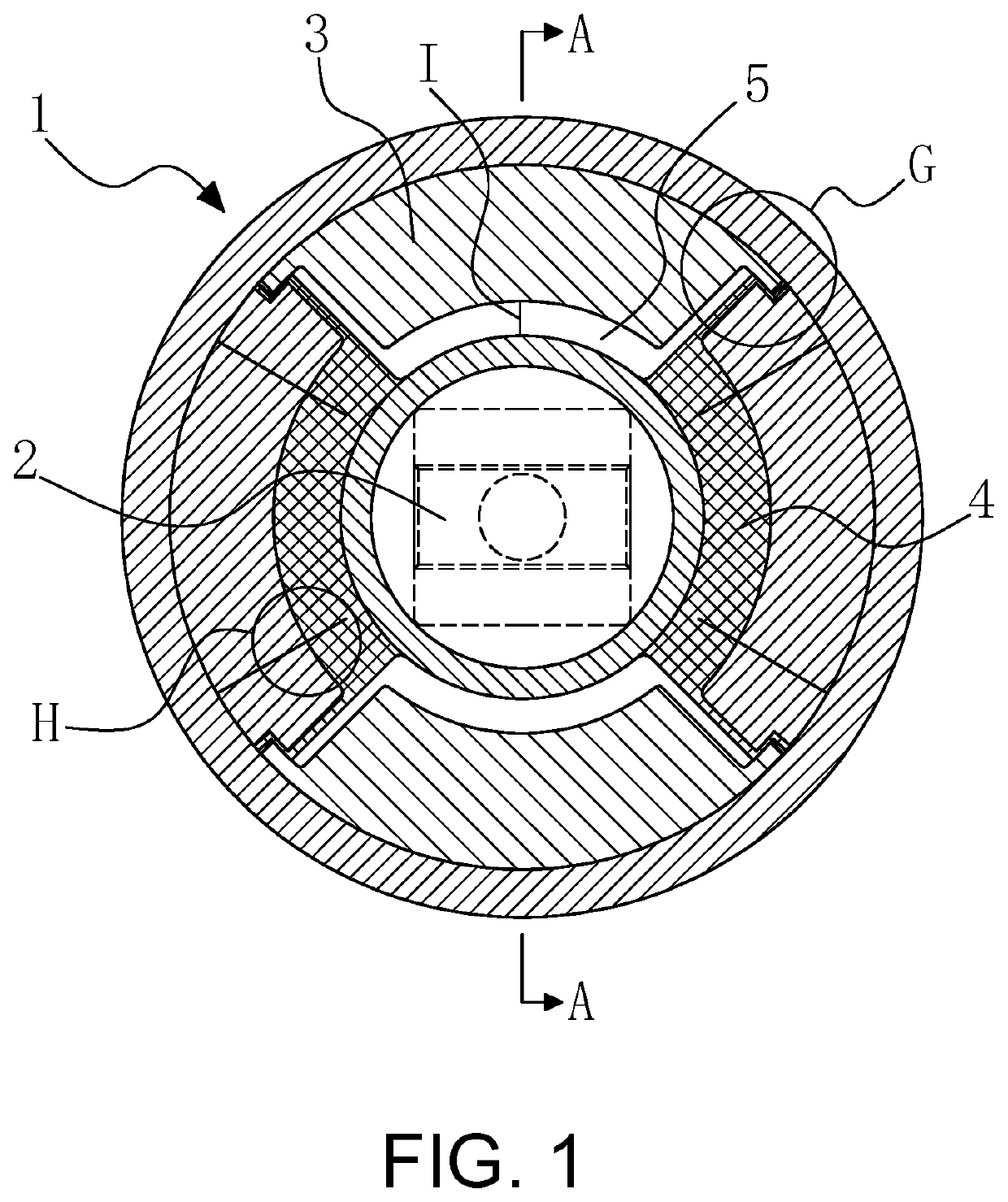
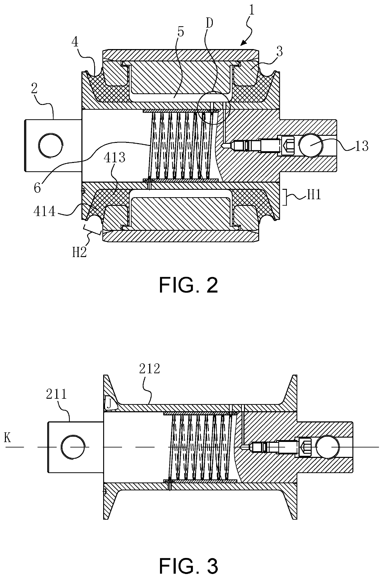
[0055]Embodiment 1: as shown in FIG. 1 and FIG. 2, a formation method for liquid rubber composite nodes with an internal groove flow channel includes the following steps. Adding a middle spacer sleeve 3 between an outer sleeve 1 and a mandrel 2, bonding the middle spacer sleeve 3 and the mandrel 2 together through rubber 4 vulcanization and assembling the integrated middle spacer sleeve and the mandrel into the outer sleeve 1. Installing a tubular flow channel in the mandrel 2. Hollowing the middle spacer sleeve 3 to form a plurality of spaces. After vulcanization, forming a plurality of interdependent liquid cavities 5 by using rubber 4 and the plurality of spaces. Arranging liquid in the plurality of liquid cavities 5 (not shown in the figure) and communicating the plurality of liquid cavities 5 through the tubular flow channel 6. The...


PUM

PropertyMeasurementUnit
βaaaaaaaaaa
βaaaaaaaaaa
lengthaaaaaaaaaa

Abstract

A formation method for liquid rubber composite nodes with a tubular flow channel is provided. The formation method includes adding a middle spacer sleeve between an outer sleeve and a mandrel, bonding the middle spacer sleeve and the mandrel together through rubber vulcanization and assembling the integrated middle spacer sleeve and the mandrel into the outer sleeve; installing a tubular flow channel in the mandrel; hollowing the middle spacer sleeve to form a plurality of spaces; after vulcanization, forming a plurality of interdependent liquid cavities by using rubber and the plurality of spaces; and arranging liquid in the plurality of liquid cavities and communicating the plurality of liquid cavities through the tubular flow channel.

Description

TECHNICAL FIELD[0001]The present invention relates to a formation method for liquid rubber composite nodes, in particular to a formation method for liquid rubber composite nodes with a tubular flow channel.DESCRIPTION OF RELATED ART[0002]According to the dynamic requirements, a tumbler node provides large radial stiffness to ensure the operational stability and improve the critical speed during linear high-speed operation (high frequency vibration) and provides small stiffness performance to ensure curve passing performance and reduce wear when passing a curve (low frequency and large amplitude). It is difficult for an ordinary node to realize the above characteristics; especially for old lines, wheel rails and lines are worn seriously and need high maintenance cost. Therefore, it is necessary to use a new product having the above characteristics, i.e., a liquid rubber composite node.[0003]Working principle of a liquid rubber composite tumbler node: two hollow cavity structures are ...

Claims


Application Information

Patent Timeline
Patent Type & Authority Applications(United States)
IPC IPC(8): F16F5/00F16F15/023
CPCF16F5/00F16F15/023F16F2238/04F16F2232/08F16F2224/048F16F2238/02F16F13/1445F16F13/1463
Inventor LUO, JUNLIU, WENSONGLIN, SHENGJIANG, ZHONGSANCHEN, JUNHUIZHANG, YUXIANGZENG, XIANHUILI, JINGZHOU, JUAN
Owner ZHUZHOU TIMES RUIWEI ANTI VIBERATION EQUIP LTD
Why Eureka
Try Eureka