Unlock instant, AI-driven research and patent intelligence for your innovation.

Three-axis rotation rate sensor including a substrate and a double rotor

a three-axis rotation rate and sensor technology, applied in the direction of speed measurement using gyroscopic effects, instruments, surveying and navigation, etc., can solve the problem of one rotation rate being measured in the x and y directions, no rotational energy being released to the surroundings, error signal or additional noise in the signal,

Pending Publication Date: 2022-07-21
ROBERT BOSCH GMBH
View PDF4 Cites 0 Cited by
  • Summary
  • Abstract
  • Description
  • Claims
  • Application Information

AI Technical Summary

Benefits of technology

The present invention provides a system of a three-axis rotation rate sensor that is robust against vibrations, decouples the smallest possible amount of energy during operation, is insensitive to electrical measuring pulses, may be implemented on a small surface area, and has high sensitivity and good surface area utilization. The rotation rate sensor allows detection of external rotation rates with regard to all three spatial directions, the drive movement being the rotors. The rotors of the sensor include deflectable seismic masses which are co-rotated during the rotary oscillation of the rotors, so that the radially extending Coriolis forces effectuate a displacement of the seismic masses in the radial direction of the rotor, which may be correspondingly detected. The rotors fulfill a dual function, and are designed in a particular space-saving manner with very good surface area utilization. The sensor requires very few mass elements and coupling elements, and is significantly less sensitive to variations in the manufacturing process.

Problems solved by technology

Therefore, no rotational energy can be released to the surroundings, regardless of the installation conditions.
External interferences such as vibrations, electrical measuring pulses, or the electronic noise of the evaluation circuit may result in the excitation of undesirable oscillation modes, which, depending on the form of oscillation, may result in an error signal or an additional noise component in the signal.
For such a system it is disadvantageous that only one rotation rate may be measured in the X and Y directions, while a measurement in the Z direction is not possible.
Due to the additional elements and their coupling structures, the three-axis rotation rate sensors are generally very complex, and include a very large number of spring elements which in particular are very soft and thus very sensitive to interference from external vibrations or electrical measuring pulses.

Method used


Image

  • Three-axis rotation rate sensor including a substrate and a double rotor
  • Three-axis rotation rate sensor including a substrate and a double rotor
  • Three-axis rotation rate sensor including a substrate and a double rotor

Examples


Embodiment Construction

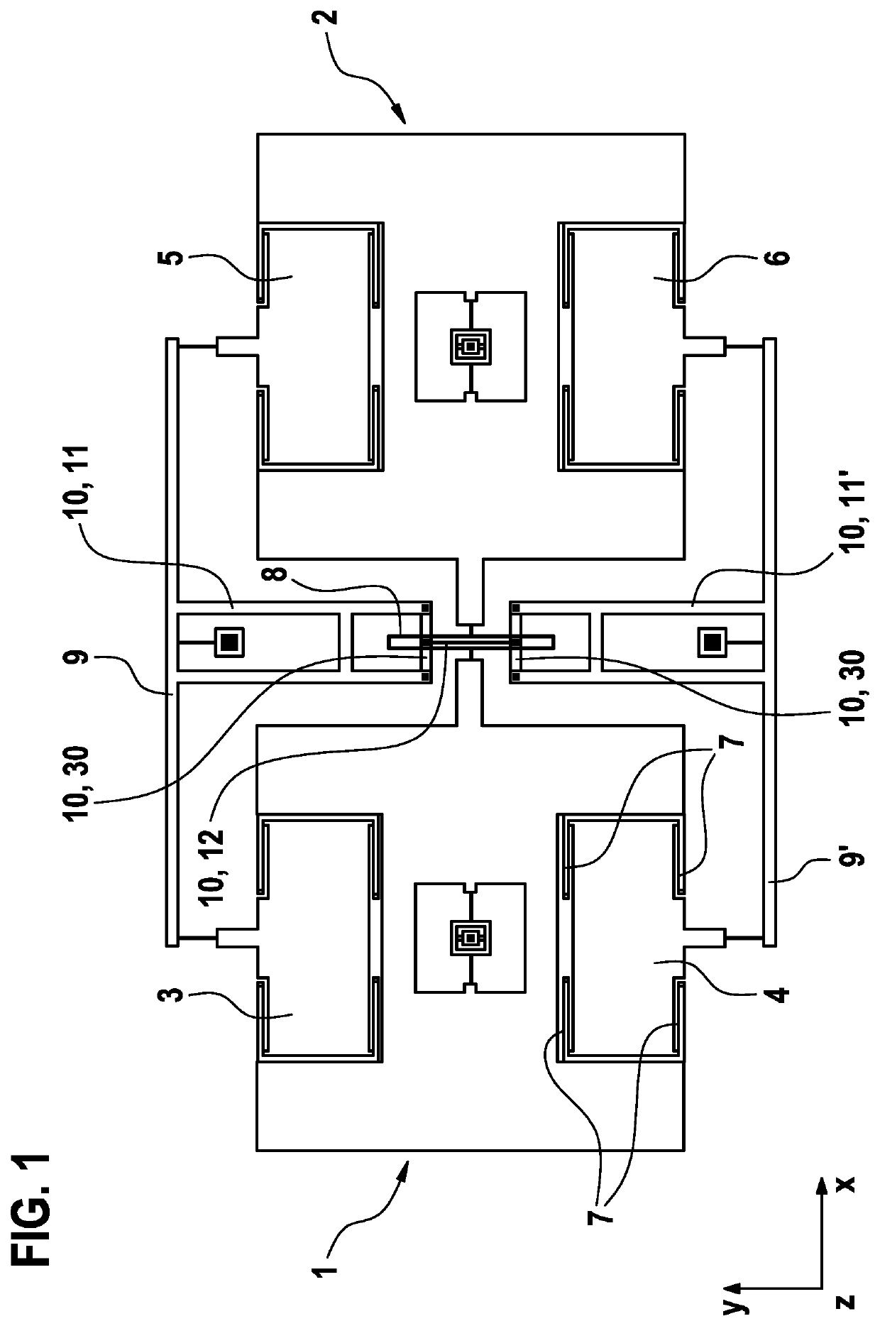
[0036]FIG. 1 schematically illustrates the sensor system according to the present invention. The base element is formed by a double rotor that oscillates in phase opposition. Two seismic masses 3, 4 and 5, 6 are respectively partitioned in the two rotors 1, 2, and are softly supported in a direction perpendicular to the oscillation axis of the rotors via springs 7. The two rotors are coupled to one another via a first coupling element 8, which in the illustrated design includes a centrally situated O-shaped section which under load is spread apart in the X direction. Each of the partitioned masses of a rotor 1, 2 are coupled to one another (mass 3 to mass 5, and mass 4 to mass 6]) via a rocker element 9 or 9′, respectively. A lateral deflection of masses 4 and 6 or 3 and 5 in phase opposition is forced by rocker elements 9, 9′ (cf. FIGS. 5A-5D). The two rocker elements 9, 9′ are connected via a second coupling element 10 made up of two additional arms 11, 11′, which in turn are conn...


PUM


Abstract

A three-axis rotation rate sensor including a substrate and a double rotor. The double rotor includes a first rotor and a second rotor which are elastically connected to one another via a first coupling element so that the two rotors are excitable to rotary oscillations in phase opposition. The first rotor includes a first seismic mass and a second seismic mass that are deflectably supported with respect to the first rotor, and the second rotor includes a third seismic mass and a fourth seismic mass that are deflectably supported with respect to the second rotor. The first mass is connected to the third mass via a first rocker element so that upon a lateral deflection of the first mass, the third mass is deflected in a direction opposite the lateral deflection of the first mass.

Description

CROSS REFERENCE[0001]The present application claims the benefit under 35 U.S.C. § 119 of German Patent Application No. 10 2021 200 483.0 filed on Jan. 20, 2021, which is expressly incorporated herein by reference in its entirety.FIELD[0002]The present invention is directed to a three-axis rotation rate sensor.BACKGROUND INFORMATION[0003]Rotation rate sensor systems in numerous specific embodiments are available in the related art. In one simple variant, for example a rotor is situated in a MEMS functional plane (XY plane) in parallel to a substrate and excited to oscillation. If an external rotation rate is present at the MEMS component in the X or Y direction, the rotor is deflected in the Z direction due to the Coriolis force. This deflection may in turn be determined via a change in capacitance with respect to stationary detection electrodes. It is advantageous to use two detection electrodes that are situated symmetrically with respect to the rotation axis, and whose difference ...

Claims


Application Information

Patent Timeline
IPC IPC(8): G01C19/5719G01C19/5712
CPCG01C19/5719G01C19/5712G01P3/483
Inventor REINMUTH, JOCHEN
Owner ROBERT BOSCH GMBH