
Optical shaping device

Pending Publication Date: 2022-07-28
HONDA MOTOR CO LTD
View PDF0 Cites 0 Cited by
  • Summary
  • Abstract
  • Description
  • Claims
  • Application Information

AI Technical Summary

Benefits of technology

The present invention provides an optical shaping device that can uniformly mix powder materials in a liquid photocurable resin without the need for a stirring mechanism. This device allows for a high shaping speed and prevents a decrease in fluidity when a large amount of powder material is mixed. The invention also improves the shape accuracy and mechanical characteristics of the final product obtained by sintering the shaped object. The shaped object is formed while the liquid photocurable resin flows in one direction in a resin tank, without storing it in the tank. This prevents separation between the photocurable resin and the powder material and allows for uniform distribution of the powder material in the shaped object. The invention is capable of improving the shaping speed and obtaining a final product with high shape accuracy and mechanical characteristics.

Problems solved by technology

As a result, the optical shaping device including the stirring device becomes large.
In addition, in a case where a photocurable resin mixed with a powder material is supplied to a resin tank from the outside and the photocurable resin is poured to a light irradiation location (shaping portion), since the photocurable resin has low fluidity, it takes time until the photocurable resin reaches the shaping portion.
As a result, the time taken to form the shaped object becomes longer.
Further, even when the powder material in the liquid photocurable resin is sufficiently mixed and stirred before shaping, if the photocurable resin is stored for a predetermined time or longer before shaping, the powder material present in the shaped object of the photocurable resin becomes non-uniform.
As a result, the shape accuracy of a final product obtained by sintering the shaped object is reduced, and the mechanical characteristics of the final product are reduced.

Method used


Image

  • Optical shaping device
  • Optical shaping device
  • Optical shaping device

Examples


Embodiment Construction

[0018]Hereinafter, a preferred embodiment of an optical shaping device according to the present invention will be described with reference to the accompanying drawings.

1. Configuration of Present Embodiment

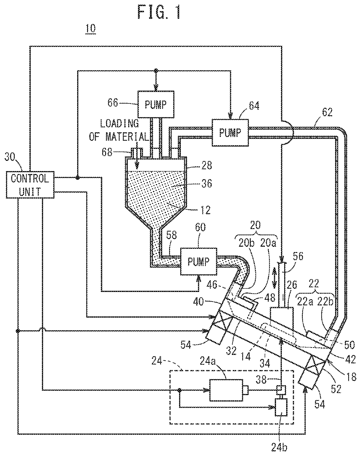
[0019]As shown in FIG. 1, an optical shaping device 10 according to the present embodiment forms a three dimensional shaped object 14 by irradiating a liquid photocurable resin 12 with light to cure the photocurable resin 12. That is, the optical shaping device 10 is a so-called 3D printer.

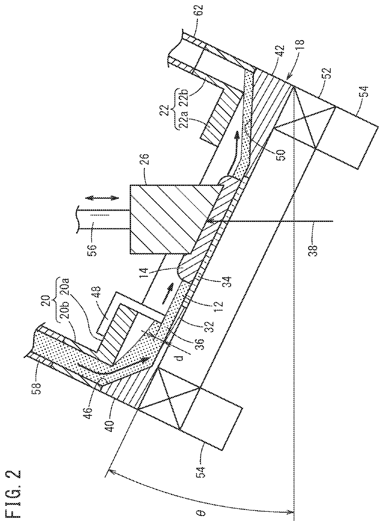
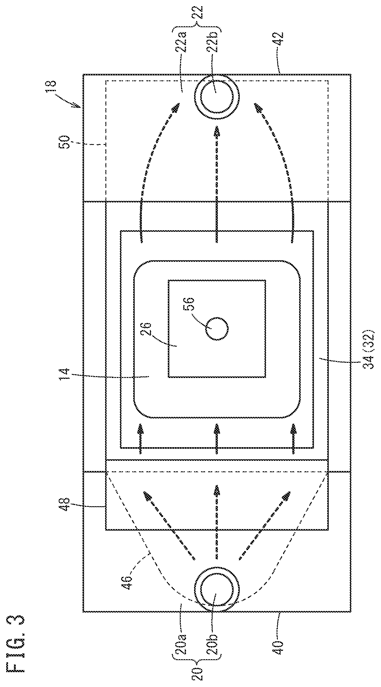
[0020]As shown in FIGS. 1 to 3, the optical shaping device 10 includes a resin tank 18, a resin supply unit 20, a resin discharge unit 22, a light irradiation mechanism 24, a holding unit 26, a tank 28, and a control unit 30.

[0021]The resin tank 18 is a substantially rectangular container having a relatively shallow depth (for example, a depth of about 5 mm), and the upper side thereof is open. A light-transmissive member 34 made of glass or the like is provided at a central portion of a bottom ...


PUM

PropertyMeasurementUnit
Temperatureaaaaaaaaaa
Angleaaaaaaaaaa
Photocurableaaaaaaaaaa

Abstract

This optical shaping device is provided with: a resin tank; a resin supply part that is provided to one end section of the resin tank and supplies a liquid photocurable resin to the resin tank; and a resin discharge part that is provided to the other end section of the resin tank and discharges the photocurable resin to the resin tank. While a shaped object is formed by irradiation of at least the liquid photocurable resin with laser light beam or a light flux, the resin tank causes the photocurable resin to flow from the one end section toward the other end section.

Description

TECHNICAL FIELD[0001]The present invention relates to an optical shaping device that forms a shaped object by irradiating a liquid photocurable resin with light to cure the photocurable resin.BACKGROUND ART[0002]Recently, stereolithography technology has been used to produce desired products.[0003]JP 3537161 B2 discloses the following. A liquid photocurable resin mixed with metal powder (powder material) is stored in a tank (resin tank), and the photocurable resin is irradiated with light from the outside to be cured. Thus, a three dimensional shaped object is formed. Thereafter, the resin is removed from the shaped object by a resin-removal step. Finally, the shaped object from which the resin has been removed is sintered to obtain a desired metal product.[0004]In addition, JP 4246220 B2 discloses the following. A shaping container (resin tank) for storing a photocurable resin and a pump are connected by a pipe, and the pump is driven to stir the photocurable resin in the shaping c...

Claims


Application Information

Patent Timeline
IPC IPC(8): B29C64/135B33Y30/00
CPCB29C64/135B33Y30/00B29C64/336B29C64/321B29C64/343Y02P10/25B22F10/12B22F12/30B33Y40/20B22F12/50B22F12/37B22F10/70B22F2202/01B22F2999/00B22F3/1021B22F3/10
Inventor KIMORI, MASAHITOTAKAHASHI, KEISUKE
Owner HONDA MOTOR CO LTD
Features
  • Generate Ideas
  • Intellectual Property
  • Life Sciences
  • Materials
  • Tech Scout
  • Unparalleled Data Quality
  • Higher Quality Content
  • 60% Fewer Hallucinations
Learn More