Co-axial via structure

a coaxial via and structure technology, applied in the direction of dielectric characteristics, printed circuit aspects, high frequency circuit adaptations, etc., can solve the problems of poor magnetic shielding efficiency, impedance mismatch problem, and large budget consumption

Pending Publication Date: 2022-07-28
UNIMICRON TECH CORP
View PDF3 Cites 0 Cited by
  • Summary
  • Abstract
  • Description
  • Claims
  • Application Information

AI Technical Summary

Problems solved by technology

It is required to add extra dielectric layers between a grounding line and a signal line by a compression process for manufacture a conventional co-axial via structure which may cause greater budget consumption.
In addition, inner circuits and outer lines within a via structure are located at different levels, and therefore impedance mismatc

Method used


Image

  • Co-axial via structure
  • Co-axial via structure
  • Co-axial via structure

Examples


Embodiment Construction

[0026]Reference will now be made in detail to the present embodiments of the invention, examples of which are illustrated in the accompanying drawings. Wherever possible, the same reference numbers are used in the drawings and the description to refer to the same or like parts.

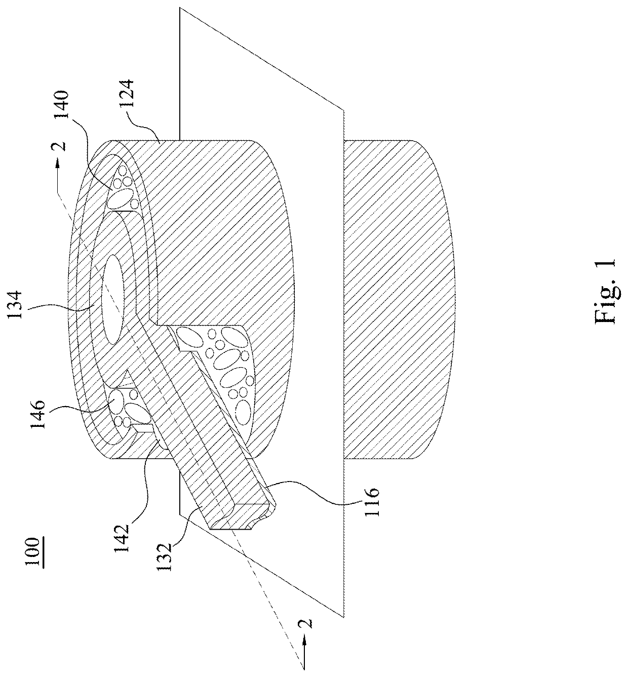
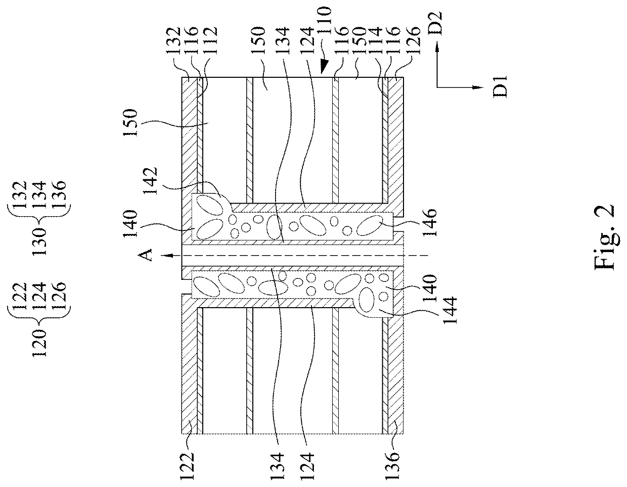
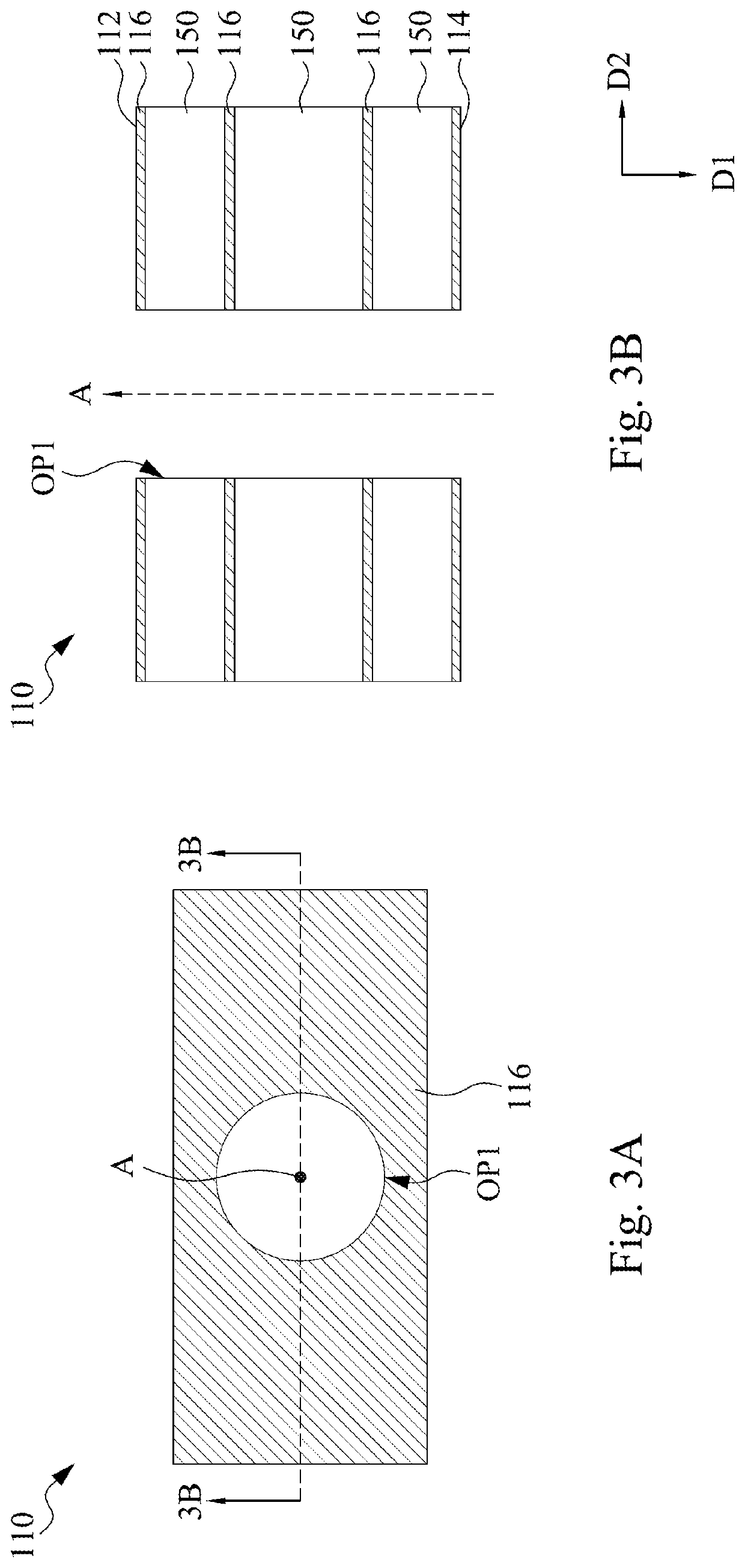
[0027]FIG. 1 is a three-dimensional view of the co-axial via structure 100 according to one embodiment of the present disclosure. FIG. 2 is a cross-sectional view taken along line 2-2 in FIG. 1. Reference is made to FIG. 1 and FIG. 2 simultaneously. The co-axial via structure 100 includes a substrate 110, a first conductive structure 120, a second conductive structure 130, and an insulating layer 140.

[0028]The substrate 110 includes a first surface 112 and a second surface 114 opposite to each other. The first conductive structure 120 includes a first circuit 122 and a first via 124, and the second conductive structure 130 includes a second circuit 132 and a second via 134. The first circuit 122 and the second...


PUM

PropertyMeasurementUnit
Electrical conductoraaaaaaaaaa
aaaaaaaaaa

Abstract

A co-axial structure includes a substrate, a first conductive structure, a second conductive structure, and an insulating layer. The substrate includes a first surface. The first conductive structure includes a first circuit deposited on the first surface and a first via penetrating the substrate. The second conductive structure includes a second circuit deposited on the first surface and a second via penetrating the substrate. The first via and the second via extend along a first direction. The first circuit and the second circuit extend along a second direction, and the second direction is perpendicular to the first direction. The insulating layer is located between the first via and the second via. The insulating layer includes a filler. The first conductive structure and the second conductive structure are electrically insulated. The first circuit and the second circuit are coplanar.

Description

CROSS-REFERENCE TO RELATED APPLICATION[0001]This application claims priority to U.S. Provisional Application Ser. No. 63 / 142,994, filed Jan. 28, 2021 and Taiwan Application Series 110137648, filed Oct. 8, 2021, which are herein incorporated by reference in their entireties.BACKGROUNDField of Invention[0002]The present invention relates to a co-axial via structure.Description of Related Art[0003]It is required to add extra dielectric layers between a grounding line and a signal line by a compression process for manufacture a conventional co-axial via structure which may cause greater budget consumption. In addition, inner circuits and outer lines within a via structure are located at different levels, and therefore impedance mismatch problem may occur. The dielectric layer deposited between the grounding line and the signal line may also have shielding notch which may cause poor magnetic shielding efficiency. In addition, since the filler material of the insulating layer usually has ...

Claims


Application Information

Patent Timeline
IPC IPC(8): H05K1/02
CPCH05K1/024H05K1/0222H05K1/0221H05K3/429H05K2201/0959H05K1/0251H05K2201/0116H05K1/112
Inventor WANG, PEI-WEINIEN, HENG-MINGCHEN, CHING-SHENGLIN, YI-PINCHENG, SHIH-LIANG
Owner UNIMICRON TECH CORP
Why Eureka
Try Eureka