Continuous ink jet printer and print head assembly therefor

a technology of ink jet printer and print head, which is applied in the direction of printing, other printing apparatus, etc., can solve the problems of electric field, large drop of charges, and further very small drops of splashback

Pending Publication Date: 2022-08-04
LINX PRINTING TECH
View PDF0 Cites 0 Cited by
  • Summary
  • Abstract
  • Description
  • Claims
  • Application Information

AI Technical Summary

Problems solved by technology

Additionally, further very small drops may be formed by splashback when drops of ink hit the surface being printed onto.
These very small drops may be electrically charged, and the charges will be trapped if they land on a surface that is electrically isolated.
If a large tr

Method used


Image

  • Continuous ink jet printer and print head assembly therefor
  • Continuous ink jet printer and print head assembly therefor
  • Continuous ink jet printer and print head assembly therefor

Examples


Embodiment Construction

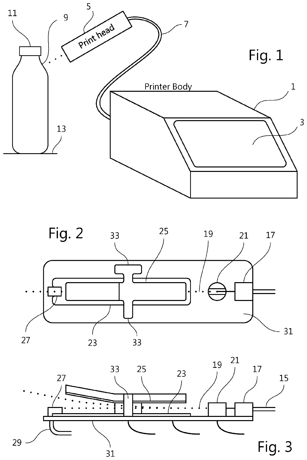
[0083]FIG. 1 shows an electrostatic deflection type continuous ink jet printer. The printer forms a continuous jet of ink and has an arrangement of electrodes for charging drops of ink and deflecting the drops electrostatically in order to print a desired pattern. The main fluid and electrical components are housed within a printer body 1. An operator communicates with the printer via a touchscreen display 3. The ink jet is formed within a print head 5, which also includes the electrode arrangement for charging and deflecting the ink drops, and the print head 5 is connected to the printer body 1 by a flexible connection 7 known as a conduit or an umbilical. Drops of ink, deflected as necessary to create the desired pattern, travel from the print head 5 and strike the surface 9 of an object 11 conveyed past the print head 5, in order to print the desired pattern on the surface 9 of the object 11. The print head 5 and the umbilical 7 form a print head assembly that may be disconnectab...


PUM


Abstract

The print head cover (83) of an electrostatic deflection inkjet printer is made of a material having an electrical surface resistivity of no more than 1012 ohms per square or an electrical volume resistivity of no more than 109 ohm metres and is electrically connected to an earth line (93, 97). This prevents build-up of electric charge on the cover (83). The resistance from the surface of the cover (83) to a place where a cover earth line (93) joins a signal earth line (97) or enters the umbilical (7) is at least 16000 times the resistance from that place to earth. This prevents an electrostatic discharge to the cover (83) disrupting the electronic circuits. The high resistance earth connection for the cover (83) avoids the need for an earthing wire braid in the umbilical (7). The cover (83) may be moulded from an antistatic or static dissipative material.

Description

FIELD OF THE INVENTION[0001]The present invention relates to an electrostatic deflection continuous ink jet printer, for example an industrial printer suitable for printing onto a succession of objects carried past the printer on a conveyor in an industrial filling, packing or processing line. Typically the objects are products such as manufactured articles or packaged food stuffs and the printer is used to print product and batch information, “use by” dates etc. The present invention also relates to a print head assembly for such a printer.[0002]In the operation of an electrostatic deflection continuous ink jet printer, a continuous jet of ink drops is formed at a print head of the printer. The print head comprises an arrangement of electrodes to trap electric charges on some or all of the ink drops and to create an electrostatic field to deflect the charged drops. The drops are deflected in flight so that only some drops are used for printing. Drops of ink that are not required fo...

Claims


Application Information

Patent Timeline
IPC IPC(8): B41J2/085
CPCB41J2/085B41J2/095B41J2/14072B41J29/38B41J2/08B41J2/02B41J2/41
Inventor COOKE, STEPHEN JOHN
Owner LINX PRINTING TECH
Why Eureka
Try Eureka