Multi-Part Railway Wheel for a Railway Vehicle

Pending Publication Date: 2022-08-04
BOCHUMER VER VERKEHRSTECHNIK GMBH
View PDF0 Cites 0 Cited by
  • Summary
  • Abstract
  • Description
  • Claims
  • Application Information

AI Technical Summary

Problems solved by technology

Due to the poor electrical conductivity of the rubber mixtures used for the elastic body or bodies, the wheel tire and the inner wheel part are electrically insulated from one another.
However, disadvantageous contact conditions between rail and wheel or between the individual parts of the wheel can lead to the result that the traction current taken up by the railway vehicle is not transmitted uniformly by all the wheels of the railway vehicle, but rather, in an extreme case, actually only by a single wheel.
Such cases can occur after strong braking, for example, if there is braking sand lying on the rail, applied to increase friction, which hinders the flow of electrical current.
This arrangement can lead to problems, in particular if the section of the inner wheel part in question consists of a light-metal material.
Such problems result from the fact that the electrical connection is influenced not only by the stress caused by the cu

Method used


Image

  • Multi-Part Railway Wheel for a Railway Vehicle
  • Multi-Part Railway Wheel for a Railway Vehicle
  • Multi-Part Railway Wheel for a Railway Vehicle

Examples


Embodiment Construction

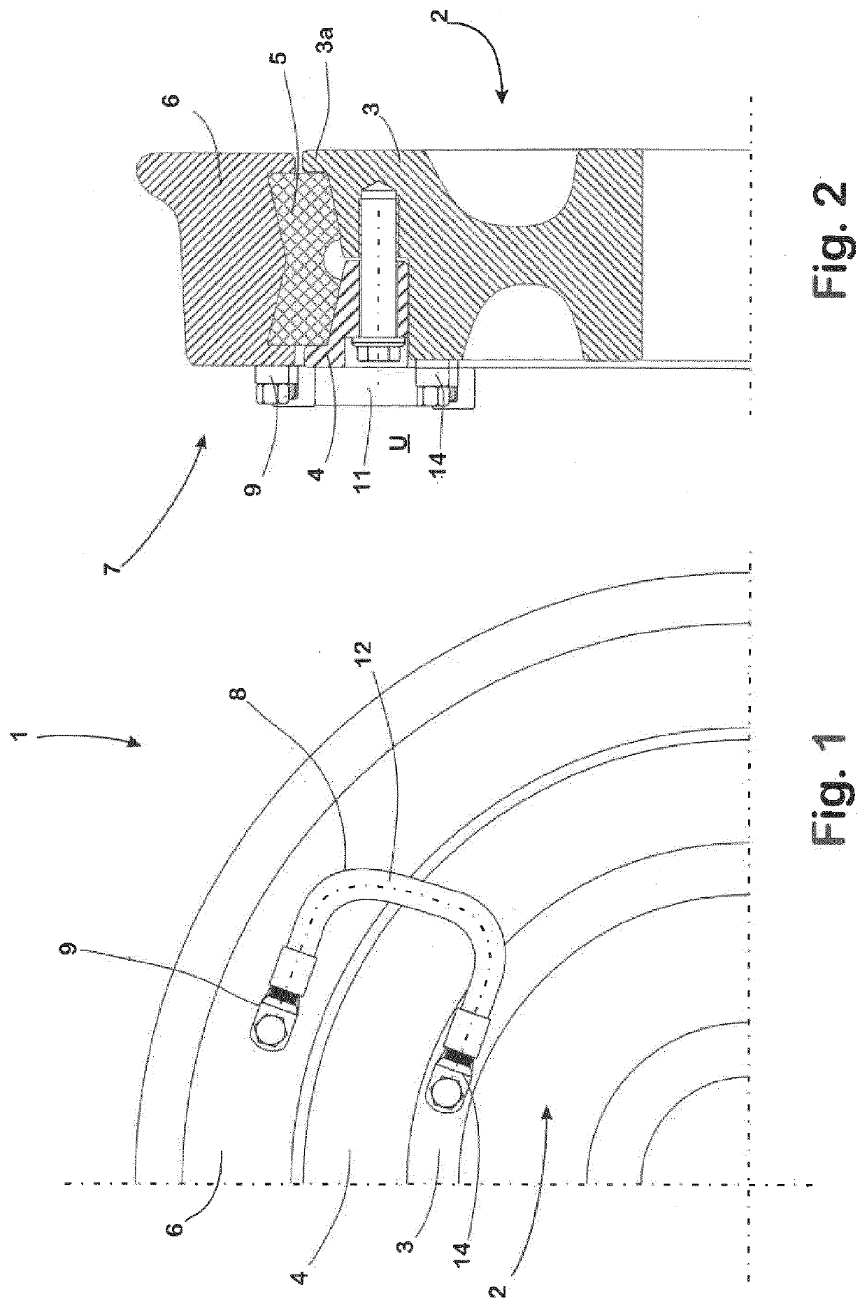
[0059]The railway wheel 1, only a quarter of which is shown in FIG. 1, comprises an inner wheel part 2, which is composed, in a known manner, of a wheel rim 3 and a clamping ring 4. The wheel rim 3 is produced from an aluminum material that is known for this purpose, whereas the clamping ring 4 can consist of material having greater strength, which is also known for this purpose.

[0060]The railway wheel 1 furthermore comprises a ring-shaped elastic body 5, which is arranged on the outside circumference of the wheel rim 3 of the inner wheel part 2, a wheel tire 6 that sits on the elastic body 5 with its inside circumference surface and, in this manner, is elastically supported on the wheel rim 3 of the inner wheel part 2 in the radial direction of the railway wheel 1. In this regard, the clamping ring 4 is braced against the wheel rim 3 of the inner wheel part 2 and the elastic body 5, in the axial direction, from the direction of an end face 7 of the railway wheel 1, by means of tens...


PUM

PropertyMeasurementUnit
Forceaaaaaaaaaa
Electrical conductivityaaaaaaaaaa
Electrical resistanceaaaaaaaaaa

Abstract

The invention relates to a multi-part railway wheel for a railway vehicle, having a wheel tire, having an inner wheel part, having at least one elastic body arranged between the wheel tire and the inner wheel part, which body acts for electrical insulation, by way of which body the wheel tire is supported on the inner wheel part, and having a current bridge that is mounted on an outside end face of the railway wheel which bridge comprises a first contact element that consists of an electrically conductive material and lies against the wheel tire with a contact surface, a second contact element that consists of an electrically conductive material and lies against the inner wheel part with its contact surface and an electrical conductor that connects the contact elements. The inner wheel part consists of a light-metal material, at least in the region in which the contact element of the current bridge, which is assigned to the inner wheel part, lies against the inner wheel part with its contact surface. In order to prevent the risk of the formation of contact corrosion at a contact location, at which a contact element of the current bridge lies against a section of the inner wheel part that consists of a light-metal material, in the case of such a railway wheel, using simple means, the invention proposes forming the contact surface of the contact element that lies against the inner wheel part on a section of the contact element that consists of corrosion-resistant, electrically conductive steel material.

Description

CROSS-REFERENCE TO RELATED APPLICATIONS[0001]This application is the United States national phase of International Application No. PCT / EP2020 / 063939 filed May 19, 2020, and claims priority to German Patent Application No. 10 2019 113 624.5 filed May 22, 2019, the disclosures of which are hereby incorporated by reference in their entirety.BACKGROUND OF THE INVENTIONField of the Invention[0002]The invention relates to a railway wheel for a railway vehicle, which is composed of a wheel tire, an inner wheel part, and at least one elastic body that acts for electrical insulation, arranged between the wheel tire and the inner wheel part, by way of which body the wheel tire is supported on the inner wheel part. In order to produce an electrical connection between the inner wheel part and the wheel tire in spite of the electrical separation brought about by means of the elastic body, a current bridge is fastened to an outer end face of the railway wheel, which bridge comprises a first conta...

Claims


Application Information

Patent Timeline
IPC IPC(8): B60B17/00B60B9/16
CPCB60B17/0034B60B9/16B60B2360/104B60B2900/141B60B2360/102B60B2360/50B60Y2200/30B60B17/0024Y02T10/86
Inventor MURAWA, FRANZ
Owner BOCHUMER VER VERKEHRSTECHNIK GMBH
Why Eureka
Try Eureka