

Zero Voltage Switching Flying Capacitor Power Converters
- Summary
- Abstract
- Description
- Claims
- Application Information
AI Technical Summary
Benefits of technology
Problems solved by technology
Method used
Image

Examples
Embodiment Construction
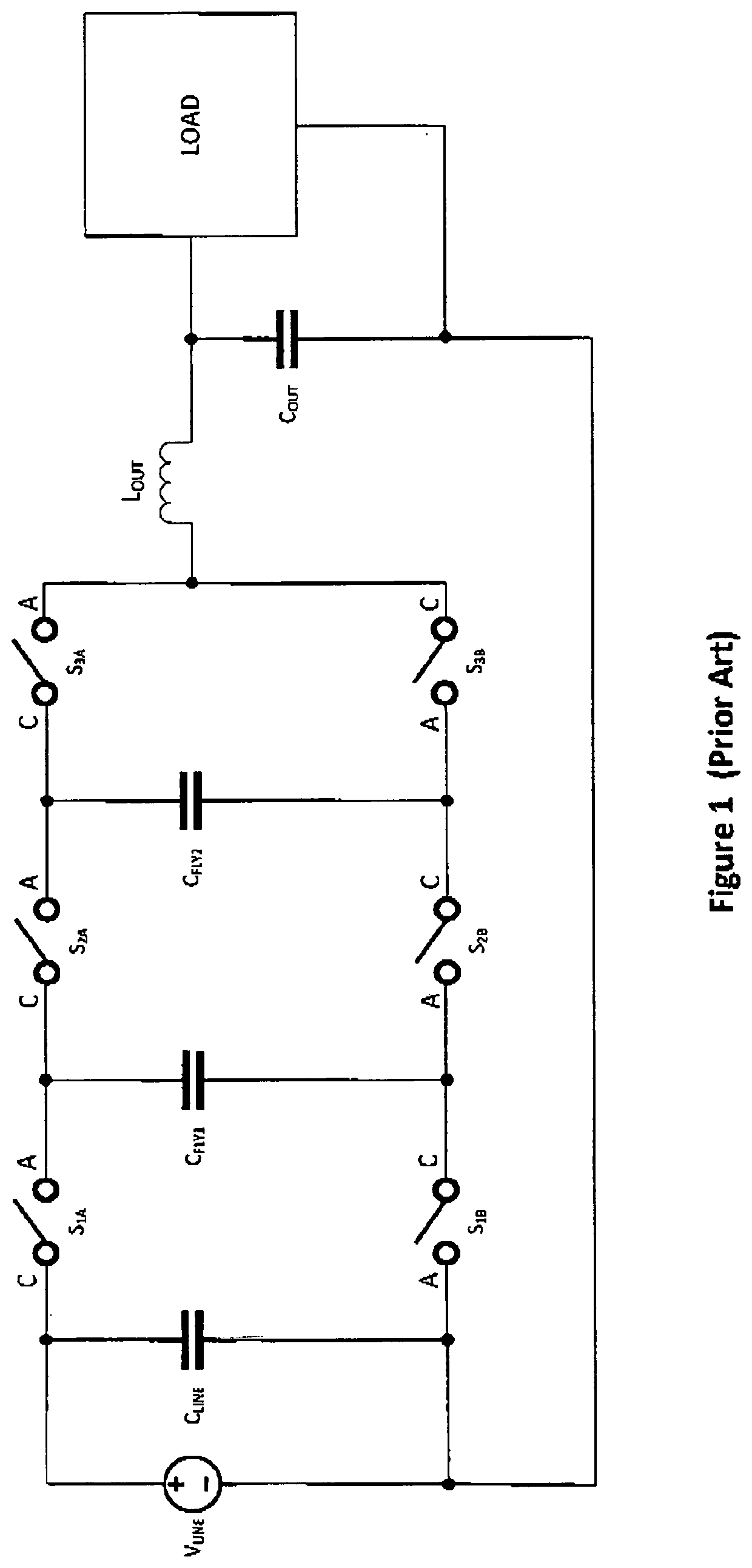
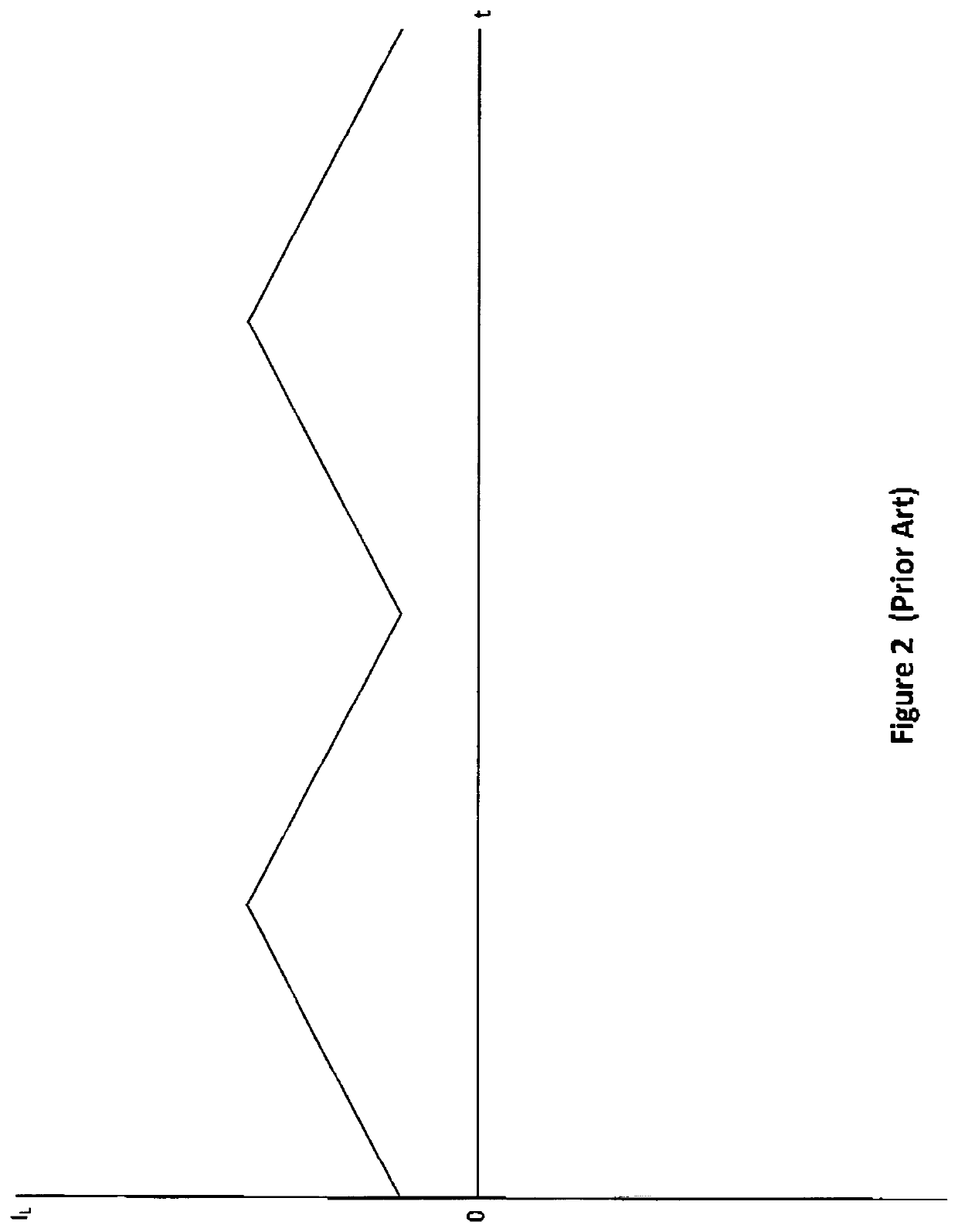
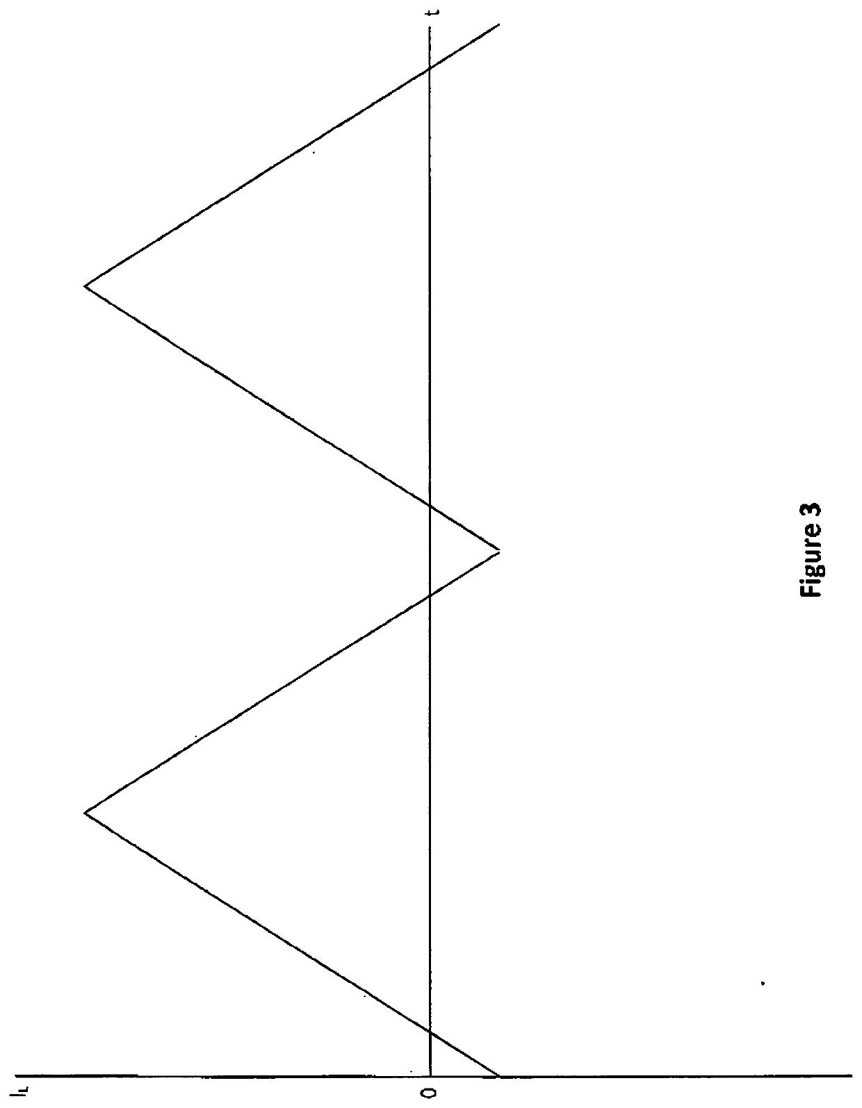
[0036]A preferred embodiment of the subject invention is illustrated in FIG. 8. The FIG. 8 Circuit is a boost converter for accomplishing power factor correction. The difference between the FIG. 8 circuit and the prior art lies in the fact that the inductor current reverses during each switching cycle, as illustrated in FIG. 3. The reversal of the inductor current means that there is stored magnetic energy in the inductor available for driving a zero voltage turn on transitions for all switches for all transitions. In an initial state, switches S1B, S2B, and S3A are on and switches S1A, S2A, and S3B are off and current in the inductor, L, is ramping up and flowing through inductor L from left to right. The current path is through the on switches and flying capacitor CFLY2, which is charging. In a first switching transition S2B is turned off. The stored magnetic energy in L tries to maintain the current in L so the voltage at node P rises, and the voltages at the C terminals of S3A a...
PUM
 Abstract
Description
Claims
Application Information