
Apparatus for Supercritical Water Gasification

a supercritical water and apparatus technology, applied in the direction of gasifier mechanical details, supercritical condition processes, bulk chemical production, etc., can solve the problems of low char, no catalysts that can produce high-quality products, and the pressure vessel of the reactor to be fabricated from very expensive alloys

Pending Publication Date: 2022-08-11
BAUDHUIN THOMAS J
View PDF0 Cites 0 Cited by
  • Summary
  • Abstract
  • Description
  • Claims
  • Application Information

AI Technical Summary

Benefits of technology

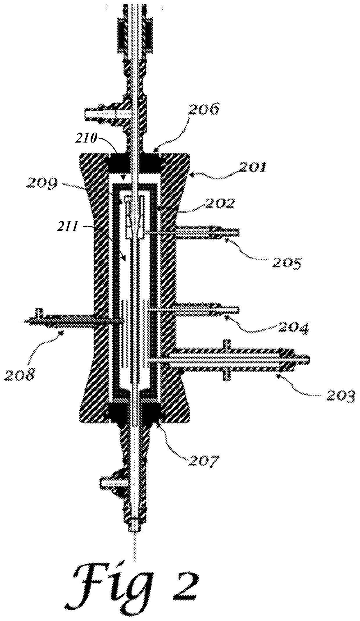
The present patent text describes using a thermal shield in a pressure vessel to protect it from high temperatures and chemical exposure. The thermal shield is made of a special material that has low thermal conductivity and low thermal expansion. The thermal shield acts as both the shell of the vessel and a conduit heat exchanger, allowing for efficient heat recovery. The thermal shield is cooled with supercritical water, which circulates naturally through the structure. This cooling system helps to maintain the thermal shield at a safe temperature. The technical effects of this approach include improved safety, efficient energy recovery, and reduced emissions.

Problems solved by technology

The combination of high pressure and high temperature has required the reactor pressure vessel to be fabricated from very expensive alloys.
However, experimental data have indicated that at this time there are no catalysts that can produce high quality product and low char production with lower operating temperatures.

Method used


Image

  • Apparatus for Supercritical Water Gasification
  • Apparatus for Supercritical Water Gasification
  • Apparatus for Supercritical Water Gasification

Examples


example

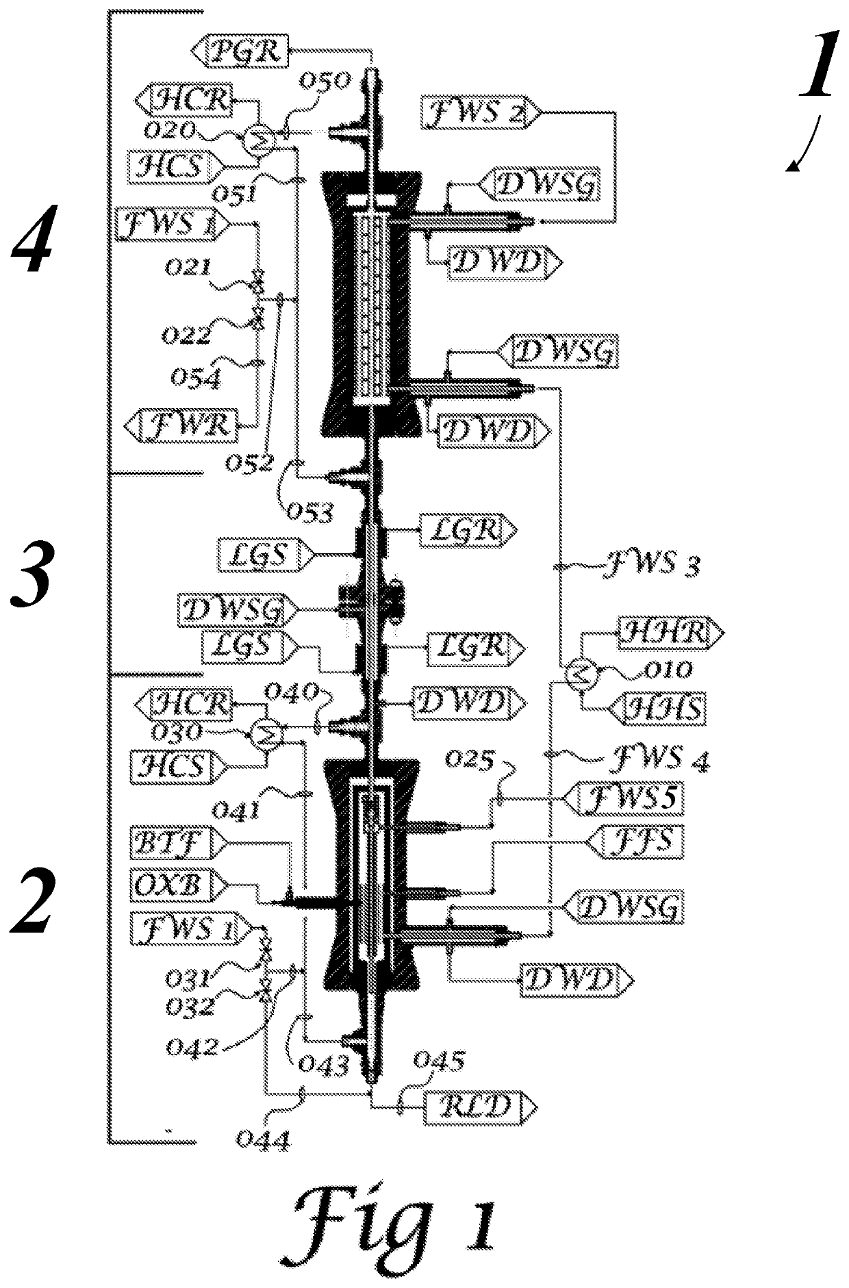
[0150]The purpose of the following indicative example is to illustrate the savings potential of the novel apparatus disclosed herein. In this example and using the current codes and standards for the construction of pressure vessels, the cost of two options will be estimated and compared. To make the options comparable both reactor shells can be designed to have a 12 inch inside diameter and will be 20 feet in length. This results in equal reactor volumes and space velocities for the supercritical water reaction to approach equilibrium. Both options will assume a design pressure of 5000 psi. Both options will be designed for a reactor internal temperature of 1450° F. Given the continuous cooling of the thermal shield combined with the ability of the thermal shield to withstand a thermal gradient between the inside and outside surfaces, the present novel apparatus can allow for a reactor shell temperature design of 750° F. When quoting costs in this example all results are rounded to...


PUM


Abstract

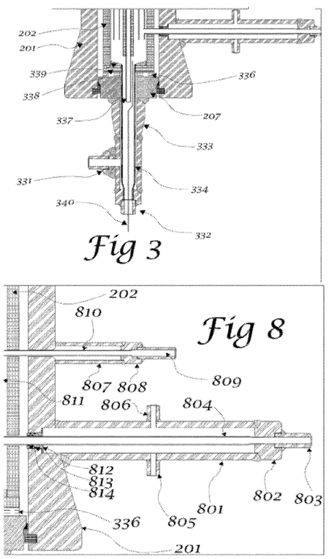
The present disclosure provides a supercritical fluid gasification system. In some embodiments, the system includes a reactor having a reactor shell including sidewalls that extend between a top reactor cover and a bottom reactor cover, where the sidewalls, the top cover, and the bottom cover enclosing a reactor shell channel. In some embodiments, the reactor includes a thermal shield positioned within the reactor shell channel, the thermal shield having sidewalls that extend between a top thermal shield cover and a bottom thermal shield cover, where the sidewalls, the top thermal shield cover, and the bottom thermal shield cover enclosing a thermal shield channel. In some embodiments, the reactor includes a fluid feed supply conduit in fluid communication with the thermal shield channel, a supercritical fluid conduit in fluid communication with the thermal shield channel, and a product conduit in fluid communication with the thermal shield channel.

Description

CROSS-REFERENCES TO RELATED APPLICATIONS[0001]This application claims priority to U.S. Patent Application No. 62 / 859,227 filed Jun. 10, 2019.STATEMENT REGARDING FEDERALLY SPONSORED RESEARCH[0002]Not Applicable.BACKGROUND OF THE INVENTION1. Field of the Invention[0003]The present disclosure generally relates to supercritical water reactors and apparatus for supercritical water gasification.2. Description of the Related Art[0004]Supercritical water is a useful solvent to break down carbonaceous materials into a mixture of simple molecules. The most common products are H2O, H2, CO2, CH4, and CO. This is classified as supercritical water gasification. Supercritical water is defined as water that is both at a pressure greater than the critical pressure, and at a temperature greater than the critical temperature. For water, the critical pressure is 3200 psi, and the critical temperature is 705° F. A key distinction between a supercritical fluid and a subcritical fluid is that coexisting l...

Claims


Application Information

Patent Timeline
IPC IPC(8): B01J3/00C10J3/78C10J3/76B01J19/00B01J3/02B01J4/00
CPCB01J3/008B01J2219/2437C10J3/76B01J19/0013B01J19/0073B01J3/02B01J4/002B01J4/005C10J2300/0979C10J2200/09B01J2219/00094B01J2219/0869B01J2219/0888B01J2219/2403B01J2219/2411C10J3/78Y02P20/54B01J2219/00822B01J2219/00831B01J2219/2423B01J2219/2434B01J2219/0886C10J3/74C10J3/84Y02P20/141B01J3/042B01J2219/00092
Inventor BAUDHUIN, THOMAS J.
Owner BAUDHUIN THOMAS J
Learn More