Method for operating an electric energy store, electric energy store, and device

Pending Publication Date: 2022-08-11
ROBERT BOSCH GMBH
View PDF4 Cites 0 Cited by
  • Summary
  • Abstract
  • Description
  • Claims
  • Application Information

AI Technical Summary

Problems solved by technology

If, for example during driving, the electrical energy storage unit of the vehicle fails, in addition to an electric drive, safety

Method used


Image

  • Method for operating an electric energy store, electric energy store, and device
  • Method for operating an electric energy store, electric energy store, and device

Examples


Embodiment Construction

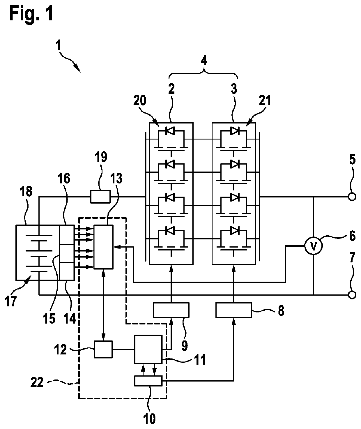
[0024]The electrical energy storage unit 1 illustrated in FIG. 1 has:[0025]at least one electrical energy storage module 18,[0026]a supervision unit 22,[0027]a switching unit 4,[0028]a charging controller 8,[0029]a discharging controller 9,[0030]a resistor 19,[0031]a first connection 5,[0032]a second connection 7 and[0033]an output voltage sensor 6 that is connected between the first and second connection and is designed to determine the voltage between the first and second connection (5, 7).

[0034]The electrical energy storage module 18 has at least one electrical energy storage cell 17 and sensors, in particular at least one cell voltage sensor 16, at least one temperature sensor 15 and a current sensor 14. The electrical energy storage module 18 preferably has a plurality of electrical energy storage cells 17 that are arranged in a series circuit. In this case, each electrical energy storage cell 17 is assigned a cell voltage sensor 16, in particular arranged connected in parallel...


PUM


Abstract

The invention relates to a method for operating an electric energy store (1), to an electric energy store (1), and to a device, having an electric energy storage module (18), a switch unit (4), and a first and second connection (5, 7). The method has the following steps which follow one another chronologically: in a first step, a signal of a sensor of the electric energy store (1) is evaluated; in a second step, a critical state of the electric energy store (1) is ascertained; in a third step, an electrically conductive connection between the electric energy storage module (18) and the first and second connection (5, 7) is interrupted in the charge direction by means of the switch unit (4), while simultaneously the electrically conductive connection between the electric energy storage module (18) and the first and second connection (5, 7) remains connected in the discharge direction.

Description

BACKGROUND OF THE INVENTION[0001]The present invention relates to a method for operating an electrical energy storage unit, to an electrical energy storage unit and to a device.[0002]US 2013 / 0169038 A1 discloses a device for the uninterrupted supply of energy to an electric vehicle, consisting of series-connected batteries and comprising a bypass switch.[0003]CN 203103992 U discloses a supervision system for battery charging management and battery discharging management.SUMMARY OF THE INVENTION[0004]The core concept of the invention in the case of the method for operating an electrical energy storage unit, having an electrical energy storage module, a switching unit and a first and second connection, is that the method comprises the following temporally successive method steps:[0005]in a first method step, a signal from a sensor of the electrical energy storage unit is evaluated, in a second method step, a critical state of the electrical energy storage unit is identified, in a thir...

Claims


Application Information

Patent Timeline
IPC IPC(8): B60L3/00H02J7/00B60L58/12
CPCB60L3/0046H02J7/0031H02J7/0047B60L2240/547B60L2250/00B60L2240/545B60L2240/549B60L58/12Y02T10/7072Y02T90/14B60L3/12B60L7/10B60L50/60B60L58/10B60L58/24H02H7/18H02H3/087H02H5/04B60L2250/10
Inventor WEBER, JOCHENSCHNEIDER, JOERGKOHN, PETERARNOLD, SABINEBARABAS, THOMAS
Owner ROBERT BOSCH GMBH
Why Eureka
Try Eureka