
Ion exchanger

a technology of ion exchanger and ion exchanger, which is applied in the direction of cation exchanger materials, separation processes, electrochemical generators, etc., can solve the problems of reducing the performance of fuel cells and increasing electrical conductivity

Pending Publication Date: 2022-08-18
TOYOTA BOSHOKU KK
View PDF0 Cites 0 Cited by
  • Summary
  • Abstract
  • Description
  • Claims
  • Application Information

AI Technical Summary

Benefits of technology

The patent describes a cooling system for an ion exchanger that reduces turbulence and pressure loss. The system uses two flow passages that join together with the same orientation, allowing the coolant to flow smoothly through the system without causing any issues. The coolant passes through ion exchange resin in a way that reduces pressure loss and increases the efficiency of the resin. Overall, this system provides improved cooling performance for the ion exchanger.

Problems solved by technology

In such a cooling circuit, an increase in the concentration of ions in the coolant may cause corrosion of metal portions in the cooling circuit or increase the electrical conductivity of the coolant, resulting in reduction of the performance of the fuel cell.

Method used


Image

  • Ion exchanger
  • Ion exchanger
  • Ion exchanger

Examples


Embodiment Construction

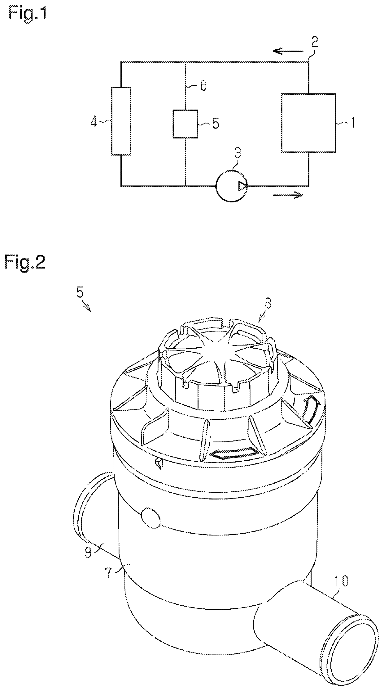
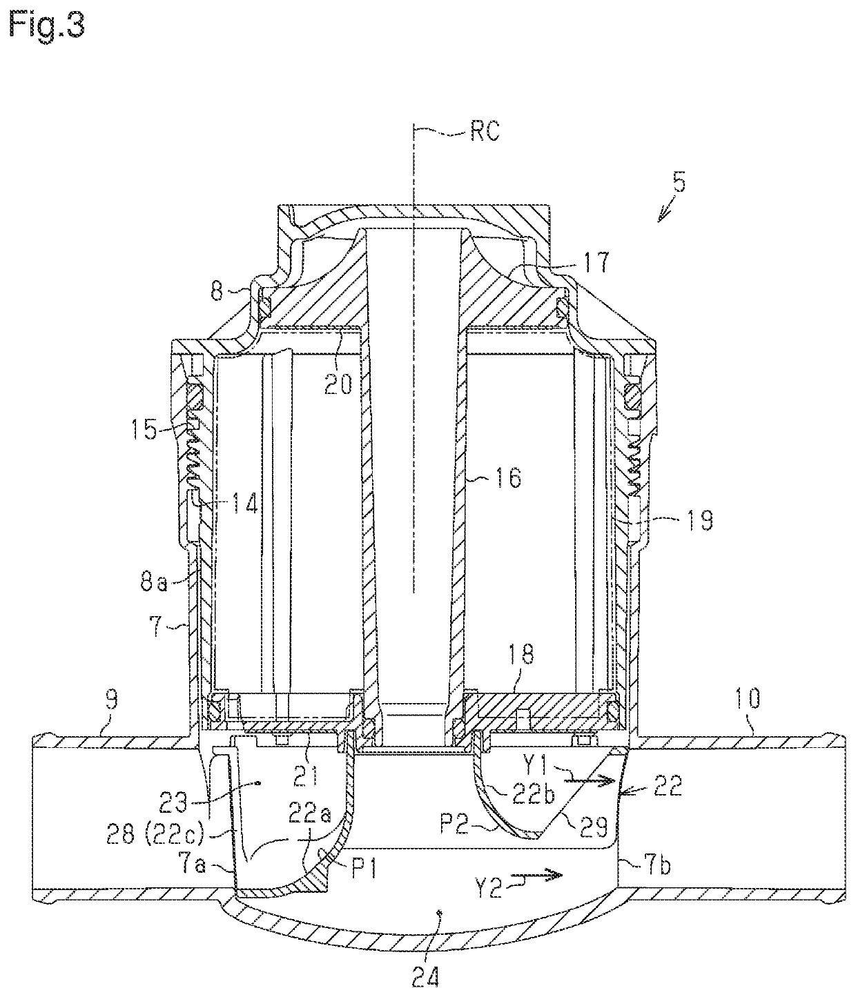
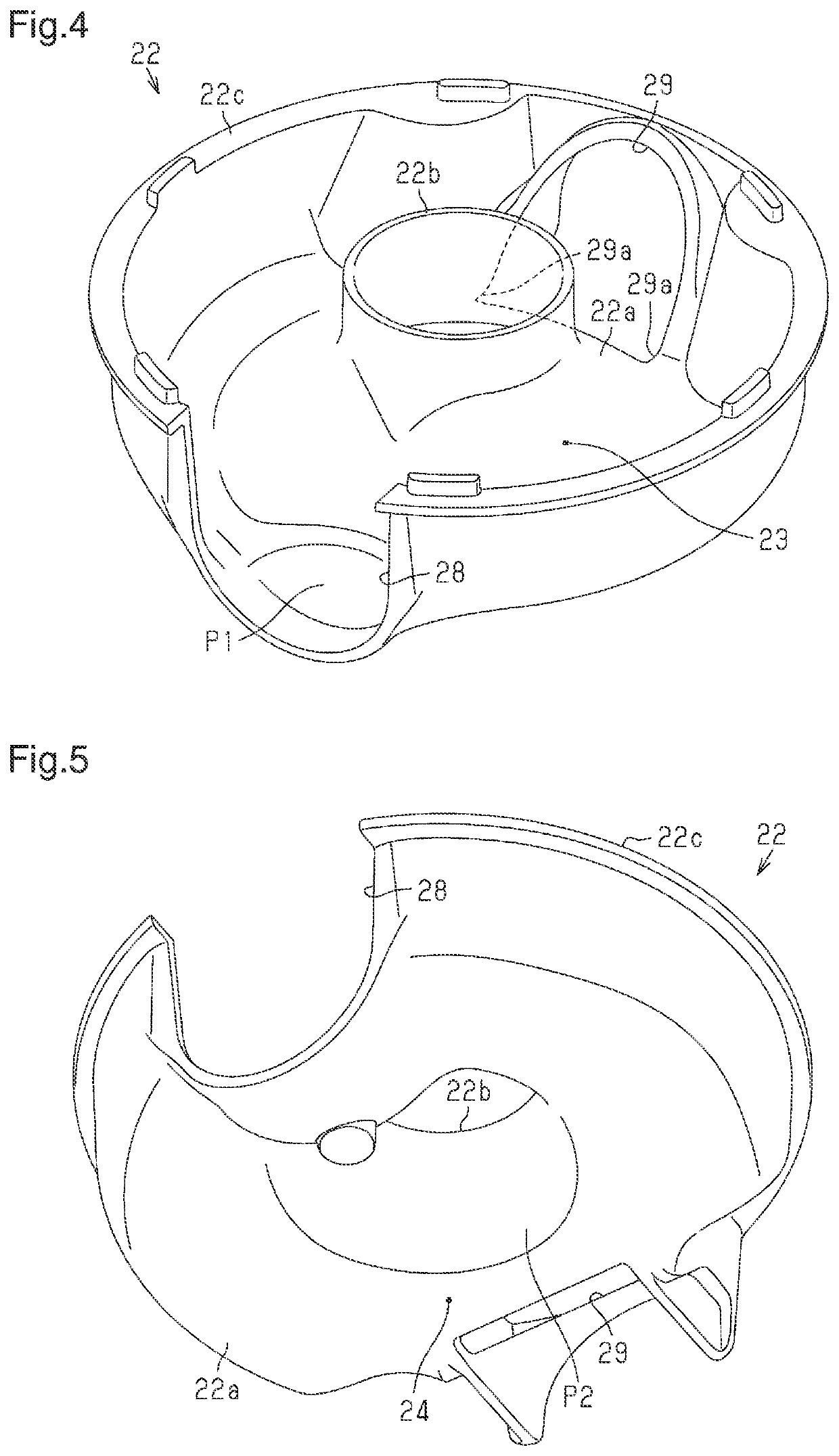
[0015]An ion exchanger according to one embodiment will now be described with reference to FIGS. 1 to 5.

[0016]As shown in FIG. 1, a vehicle equipped with a fuel cell 1 is provided with a cooling circuit 2, in which coolant flows to cool the fuel cell 1. A coolant containing ethylene glycol (long life coolant) or the like is used. The cooling circuit 2 includes a pump 3, and is configured to drive the pump 3 to circulate the coolant.

[0017]In the cooling circuit 2, the fuel cell 1 is arranged in a section on the downstream side of the pump 3. The cooling circuit 2 includes a radiator 4 in a section that is downstream of the fuel cell 1 and upstream of the pump 3. The fuel cell 1, of which the temperature increases during power generation, is cooled by the coolant circulating through the cooling circuit 2 and passing through the fuel cell 1. When heated by taking heat from the fuel cell 1, the coolant is cooled by the outside air when passing through the radiator 4, and then flows to t...


PUM

PropertyMeasurementUnit
distanceaaaaaaaaaa
heightaaaaaaaaaa
temperatureaaaaaaaaaa

Abstract

An ion exchanger includes a housing, a tube member, and an ion exchange resin. The housing includes an inlet port and an outlet port. The tube member is arranged inside the housing. The ion exchange resin is arranged between the tube member and the housing. A first flow passage and a second flow passage are formed in the housing. The first flow passage is configured to cause the coolant that has flowed in through the inlet port to flow directly to the outlet port. The second flow passage is configured to cause the coolant that has flowed in through the inlet port and passed through the ion exchange resin to flow to the outlet port. The first flow passage and the second flow passage are formed to join together in a state of being oriented in a same direction toward the outlet port.

Description

TECHNICAL FIELD[0001]The present disclosure relates to an ion exchanger.BACKGROUND ART[0002]A vehicle such as an automobile equipped with a fuel cell includes a cooling circuit for the purpose of suppressing a temperature increase of the fuel cell at the time of power generation. The cooling circuit is configured such that coolant for cooling the fuel cell flows through the cooling circuit. In such a cooling circuit, an increase in the concentration of ions in the coolant may cause corrosion of metal portions in the cooling circuit or increase the electrical conductivity of the coolant, resulting in reduction of the performance of the fuel cell. Therefore, such a cooling circuit includes an ion exchanger to remove ions contained in the coolant through ion exchange using ion exchange resin.[0003]For example, Patent Document 1 discloses such an ion exchanger. This ion exchanger includes a housing, a tube member, and ion exchange resin. The housing includes an inlet port, into which co...

Claims


Application Information

Patent Timeline
Patent Type & Authority Applications(United States)
IPC IPC(8): B01D15/18B01D15/36H01M8/04044B01J47/024
CPCB01D15/18B01D15/361H01M2250/20B01J47/024H01M8/04044H01M8/04C02F1/42B01J47/022Y02E60/50
Inventor OHIRA, JUNKOYOSHIDA, TOMOHIROYABE, SHINGOKAWAMOTO, MINETAKA
Owner TOYOTA BOSHOKU KK
Learn More