
System and method for material density distribution survey based on cosmic muon detection

a technology of cosmic radiation and density distribution, applied in the field of material density investigation based on cosmic radiation muon detection, can solve the problems of limiting the accuracy of density surveys, not being able to determine the density variation of natural materials, and lack of directional (angular) sensitivity in many density measurement techniques

Pending Publication Date: 2022-09-08
MUON SOLUTIONS OY
View PDF4 Cites 2 Cited by
  • Summary
  • Abstract
  • Description
  • Claims
  • Application Information

AI Technical Summary

Benefits of technology

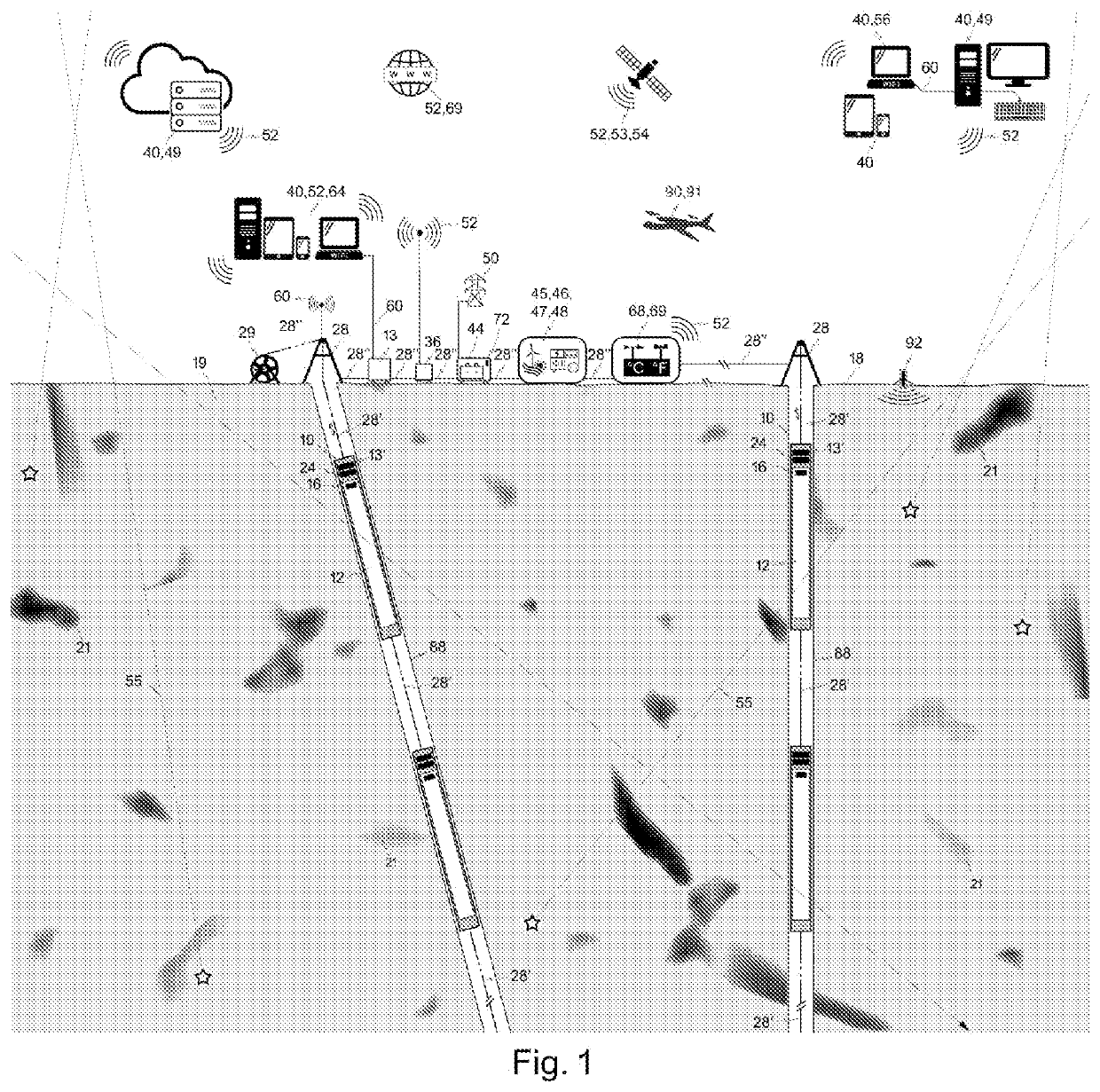
The patent describes a modification to a muon detection system that allows several detectors to be placed in a single borehole or multiple boreholes simultaneously. This results in a reduction in the total duration of the surveys. The system can also be modified to perform 2D and 3D imaging, which can provide valuable information about the density distribution in materials being studied. Additionally, the system can be used for long-term or stationary density surveys and monitoring, which can help better understand changes in material densities over time. The detector apparatus can be powered by a single set of connected auxiliaries, reducing power consumption, and can be transported to their desired measurement positions by robotic means.

Problems solved by technology

It is seldom possible to determine density variations in natural materials with good accuracy using conventional geophysical survey methods such as gravimetric density surveys.
Moreover, the lack of directional (angular) sensitivity in many density measurement techniques hinders density surveys wherever accurate spatial sensitivity is required.
This inherited problem of such instruments (commonly known as “muon telescopes”) limits their usage to the areas where there are topographic highs or an access to the underground galleries or tunnels below the volume of interest.
One known problem in the state of the art are requirements arising from varying measurement conditions, such as long distances from an electric power distribution network, have been taken into account poorly if at all.
This severely hampers their usage outside the electric power distribution networks.
Another known problem in the state of the art is sparse flexibility of the systems to be utilised in different kinds of material and measurement campaign requirements.
Another known problem in the state of the art is the large size and geometry of such muon detectors.
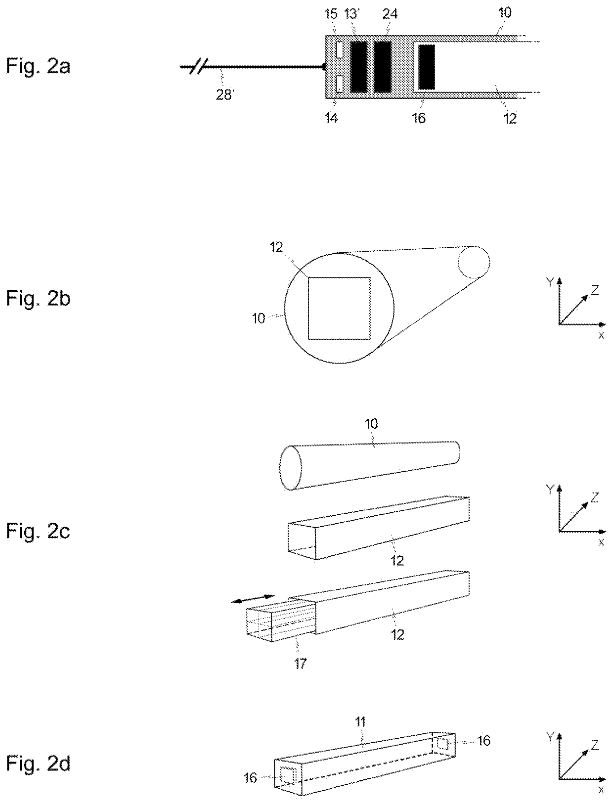
Therefore such muon detectors are utterly unfitting to most commonly used boreholes, such as those of 76.3 mm or less in diameter.
Yet another known problem hampering the present muon detection systems is a large amount of manual labour and logistics and a lot of required operational maintenance (and hence difficult to design to work autonomously), especially while using gas-filled particle detectors.

Method used


Image

  • System and method for material density distribution survey based on cosmic muon detection
  • System and method for material density distribution survey based on cosmic muon detection
  • System and method for material density distribution survey based on cosmic muon detection

Examples


Embodiment Construction

[0078]The embodiments in the following detailed description of the muon detection system 100 and the invention as a whole are examples only. Hence someone skilled in the art can implement the basic idea of the invention also in some other manner than that explained in the description. Most embodiments can be actualised in a variety of combinations with other embodiments. Most embodiments may also contain a number of connected advantageous auxiliaries, or no such auxiliaries at all. Though the description may refer to a certain embodiment or embodiments in several places, this does not imply that the reference is directed towards only one described embodiment or that the described characteristic is usable only in one described embodiment. The individual characteristics of a plurality of embodiments may be combined and new embodiments of the invention may thus be provided.

[0079]In order to assist to fully understand the invention, the presented exemplary embodiments and detailed descr...


PUM


Abstract

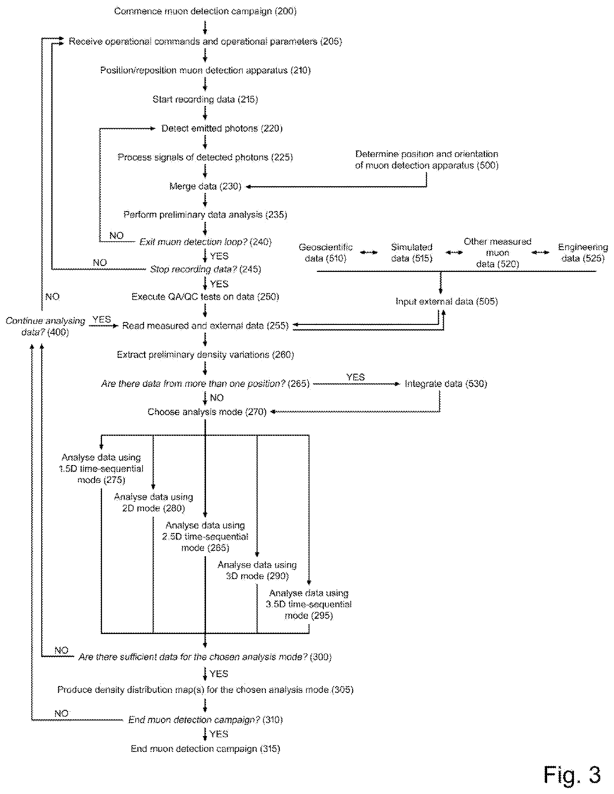
Provided herein is a system and method designed for measuring and recording, in three-dimensional space, an attenuation of cosmic-ray induced muon particle flux through a material. The attenuation of the said muons determines density variations in the said material in terms of their density, depth, shape and size. The muon data may be combined with various other data types. The passing muons are detected and recorded by one or a plurality of muon detection apparatus designed to be robust and shock resistant. If needed, each individual muon detection apparatus may be controlled remotely or automatically. The muon detection system may be powered by an energy storage device that may be recharged using renewable energy, aggregate or electric grid. The invention comprises methods steps allowing density characterisation of the material in various dimensions, including those over time.

Description

TECHNICAL FIELD[0001]The present invention generally relates to material density investigation based on cosmic-ray muon detection (cosmic ray muography) and more particularly geological structure and density variation investigation based on this investigation method. Cosmic-ray muography can be divided into muon radiography and muon tomography.BACKGROUND ART[0002]The Earth's atmosphere is constantly bombarded by particles called cosmic rays consisting of high-energy protons and atomic nuclei that interact with the Earth's atmosphere. These interactions generate particle cascades that may contain an extremely large number of secondary elementary particles such as muons. Before decaying the near-light-speed atmospheric muons can penetrate to the Earth's surface. High energy and heavy mass carry muons deep in material with relatively straight trajectories. Depending on the muon energy the penetration depth can be up to kilometres. The number of muons detected underground depends on the...

Claims


Application Information

Patent Timeline
IPC IPC(8): G01N9/24G01V5/00G01V5/04
CPCG01N9/24G01V5/005G01V5/04G01T1/169G01T1/2006G01T1/2018G01T1/202G01T1/203G01T1/204G01V5/226G01V5/22
Inventor HOLMA, MARKOKUUSINIEMI, PASI
Owner MUON SOLUTIONS OY
Learn More