
A bidirectional dc-ac conversion circuit and a starting method thereof

Pending Publication Date: 2022-09-22
SANTAK ELECTRONICS SHENZHEN
View PDF20 Cites 0 Cited by
  • Summary
  • Abstract
  • Description
  • Claims
  • Application Information

AI Technical Summary

Benefits of technology

The present invention is a circuit that can convert DC power to AC power without causing damage to the components. It achieves this by avoiding the sudden surge of electric current when the circuit is turned on. This allows for safer and more efficient use of the circuit.

Problems solved by technology

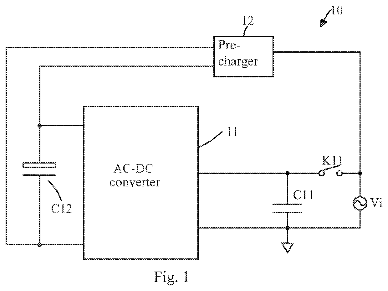
At this time, the alternating current of the AC power supply Vi is directly applied across the input capacitor C11 via the conductive switch K11, so that there is a very large inrush current in the input capacitor C11, and the switch K11 and the input capacitor C11 are easily damaged.

Method used


Image

  • A bidirectional dc-ac conversion circuit and a starting method thereof
  • A bidirectional dc-ac conversion circuit and a starting method thereof
  • A bidirectional dc-ac conversion circuit and a starting method thereof

Examples


first embodiment

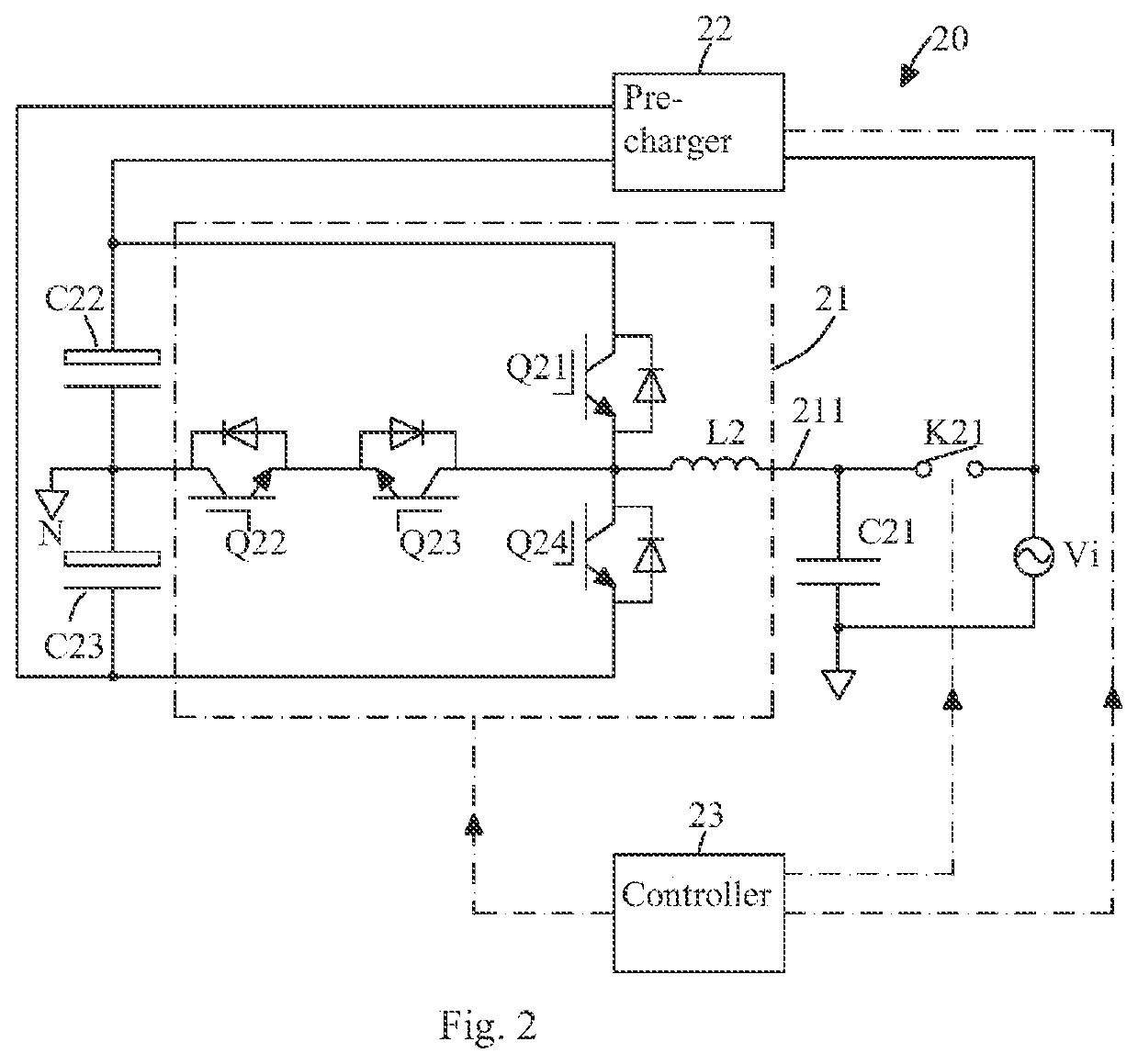
[0033]FIG. 2 is a circuit diagram of a bidirectional DC-AC conversion circuit according to the present invention. As shown in FIG. 2, the bidirectional DC-AC conversion circuit 20 includes a T-type three-level converter 21, a pre-charger 22, a switch K21, an input capacitor C21, a positive DC bus capacitor C22, a negative DC bus capacitor C23, and a controller 23 for controlling the T-type three-level converter 21, the pre-charger 22, and the switch K21.

[0034]The input of the pre-charger 22 is connected to the AC power supply Vi, and the output of the pre-charger 22 is connected to the positive terminal of the positive DC bus capacitor C22 and the negative terminal of the negative DC bus capacitor C23. The negative terminal of the positive DC bus capacitor C22 and the positive terminal of the negative DC bus capacitor C23 are connected to a neutral point N.

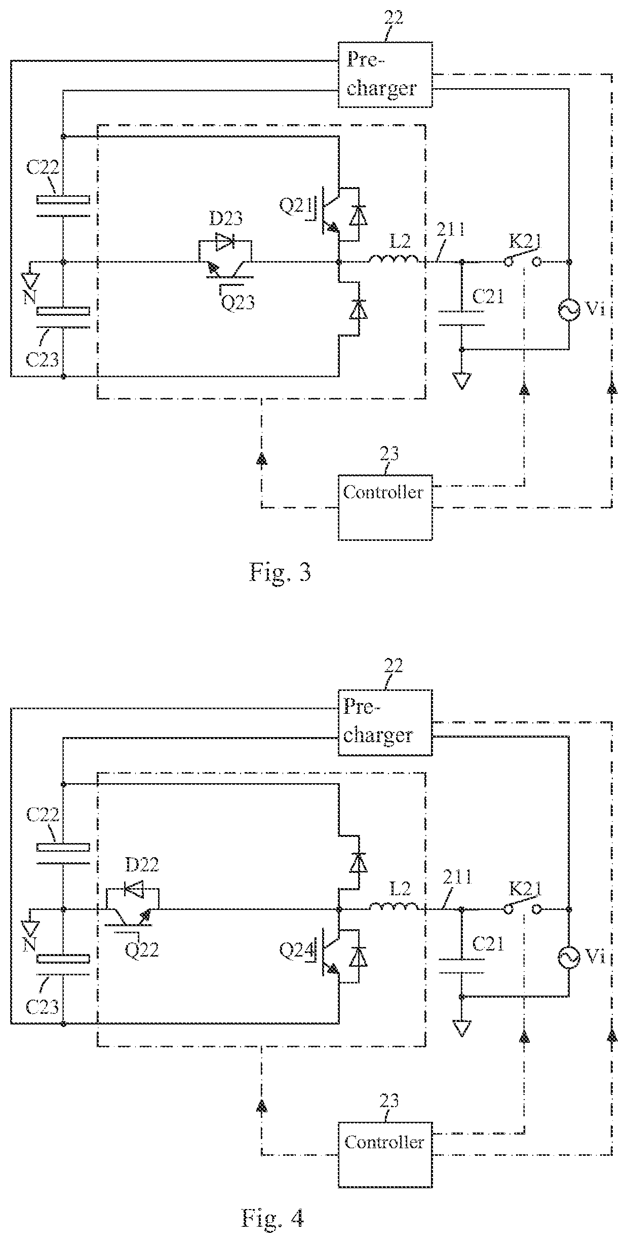
[0035]The T-type three-level converter 21 comprises switching transistors Q21, Q22, Q23, and Q24 and an inductor L2. The switchi...

second embodiment

[0044]FIG. 5 is a circuit diagram of a bidirectional DC-AC conversion circuit according to the present invention. As shown in FIG. 5, the bidirectional DC-AC conversion circuit 30 is substantially the same as the bidirectional DC-AC conversion circuit 20 shown in FIG. 2, except that the T-type three-level converter 21 is replaced with an I-type three-level converter 31.

[0045]The I-type three-level converter 31 comprises switching transistors Q31, Q32, Q33, and Q34 which are successively connected between the positive terminal of positive DC bus capacitor C32 and the negative terminal of negative DC bus capacitor C33, and a diode D35, a diode D36, and an inductor L3. The positive electrode of the diode D35 and the negative electrode of the diode D36 are connected to a neutral point, the negative electrode of the diode D35 is connected to a node formed by the connection of the switching transistors Q31 and Q32, and the positive electrode of the diode D36 is connected to a node formed ...


PUM


Abstract

The present invention provides a bidirectional DC-AC conversion circuit and a starting method thereof, wherein the bidirectional DC-AC conversion circuit comprises: a bidirectional DC-AC converter; an input capacitor connected to an AC input of the bidirectional DC-AC converter; a bus capacitor connected to a DC output of the bidirectional DC-AC converter; a switch connected between a positive terminal of the input capacitor and an AC power supply; a pre-charger, having an input connected to the AC power supply, and an output connected to the DC output of the bidirectional DC-AC converter; and a controller configured to convert the voltage across the bus capacitor into an inverting voltage and output it to the input capacitor before controlling the switch to turn on. The bidirectional DC-AC conversion circuit of the present invention can reduce inrush current in the input capacitor.

Description

TECHNICAL FIELD[0001]The present invention relates to the field of converters, and in particular to a bidirectional DC-AC conversion circuit and a starting method thereof.BACKGROUND ART[0002]FIG. 1 is a circuit diagram of an AC-DC conversion circuit in the prior art. As shown in FIG. 1, the AC-DC conversion circuit 10 includes an AC-DC converter 11, an input capacitor C11 connected to an AC input of the AC-DC converter 11, a bus capacitor C12 connected to a DC output of the AC-DC converter 11, and a pre-charger 12, the input of which is connected to the AC power supply Vi, and the output of which is connected to two ends of the bus capacitor C12. The AC power supply Vi is connected to an AC input of the AC-DC converter through a switch K11, and the AC-DC converter 11 is configured to rectify the alternating current of the AC power supply Vi into direct current and store it on the bus capacitor C12.[0003]When the AC-DC conversion circuit 10 is started, a control device (not shown in ...

Claims


Application Information

Patent Timeline
IPC IPC(8): H02M7/5395H02M7/487H02M3/335
CPCH02M7/5395H02M7/487H02M3/33584H02M7/797H02M1/36H02M1/32
Inventor YANG, YUEZHANG, DENGKEHAO, YULONG
Owner SANTAK ELECTRONICS SHENZHEN
Learn More