Control system and method for the rotor side converter of a doubly-fed induction generator in a wind turbine

a control system and double-fed technology, applied in the control system, control system, ac network circuit arrangement of electric generators, etc., can solve the problems of poor performance under fault or contingency conditions, no known vector control or dual vector control technique makes the most of converter performance or optimize operation, and neither provide a full regulation capacity over the negative sequen

Pending Publication Date: 2022-09-22
GAMESA INNOVATION & TECH SA
View PDF4 Cites 0 Cited by
  • Summary
  • Abstract
  • Description
  • Claims
  • Application Information

AI Technical Summary

Benefits of technology

[0050]FIG. 2 shows a scheme of the control system for the rotor side...

Problems solved by technology

Vector control operation is acceptable enough under usual operating conditions, but it provides poor performance under fault or contingency conditions, such as for example voltage dips and overvoltage.
However, none of the known vector control or dual vector control techniques make the most of the converter performance or optimize operation thereof provided the thermal limitations, and they neither provide a full regulation capacity over the negative sequence in the most severe unbalanced dips.
However, the systems require a high computational load, since otherwise the power quality would be seriously affected, something which is highly penalized by the grid codes (GCs).
As the nominal power of the generating unit increases, the magnitude of these currents becomes dangerously nearer the ultimate tensile strength of existing low-voltage power electronic semiconductors, the isolated gate bipolar transistors (IGBT), thus f...

Method used


Image

  • Control system and method for the rotor side converter of a doubly-fed induction generator in a wind turbine
  • Control system and method for the rotor side converter of a doubly-fed induction generator in a wind turbine

Examples


Embodiment Construction

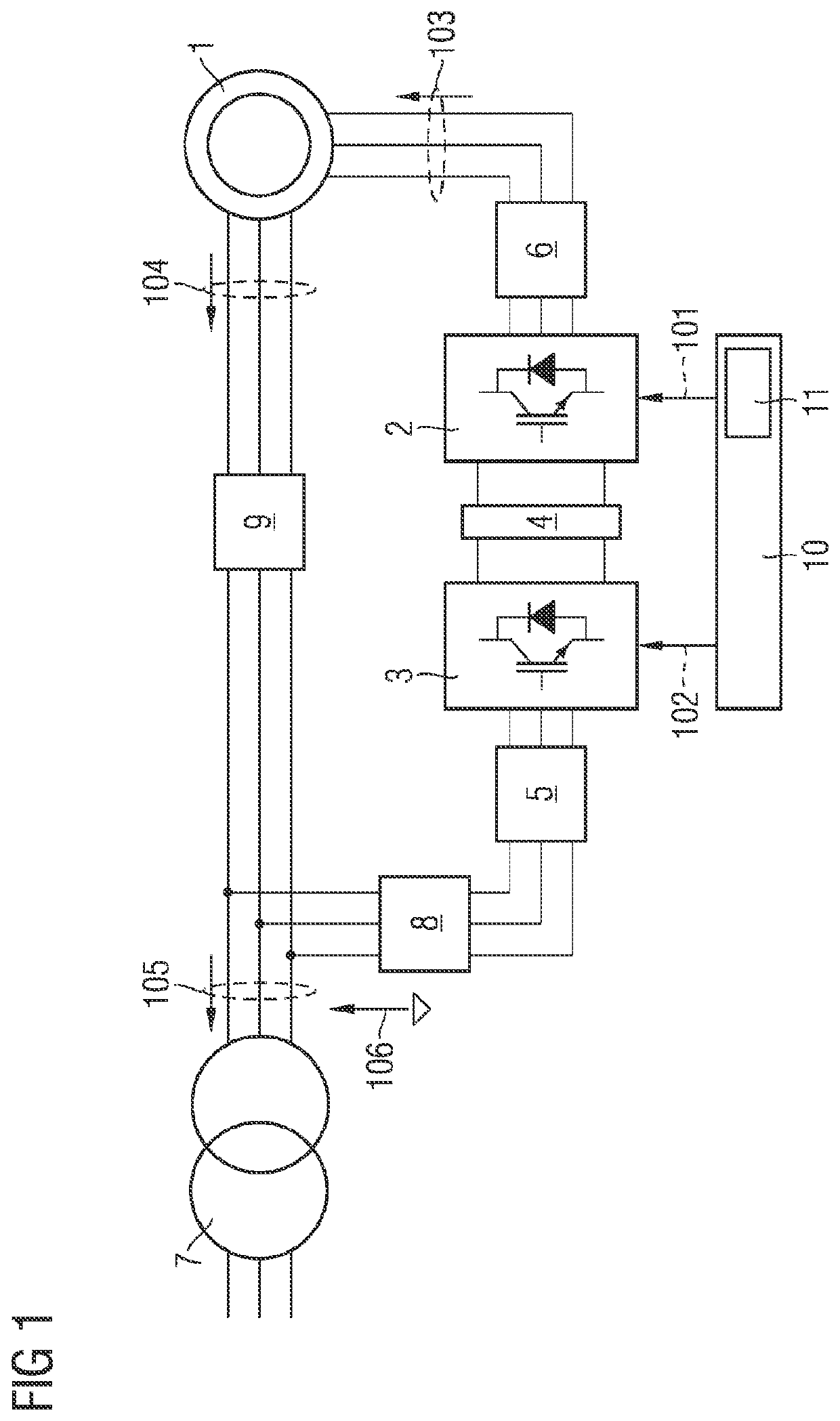
[0051]The following is a detailed description of the electric system of a doubly-fed induction generator (1) of a wind turbine and the associated control method for the rotor side converter (2) of the present invention. The winding of the doubly-fed induction generator (1) is connected to a rotor three-phase bridge (2). The rotor side converter shares its DC connection (4) with a three-phase grid bridge (3). The three-phase AC connection of the grid bridge (3) may comprise a three-phase power filter (5). Likewise, the AC three-phase connection of the rotor side converter (2) may comprise a three-phase power filter (6). The stator winding and the AC three-phase connection of the grid bridge are connected to the low voltage winding of a three-phase boost transformer (7). Both the stator winding and the AC three-phase connection of the grid bridge may have contactors (8) and switches (9), so as to make electric operation easier and guarantee protection. Both the rotor side converter (2...


PUM


Abstract

A control method for the rotor side converter of a doubly-fed induction generator in a wind turbine for disturbances in the electric grid is provided. A control system includes a calculating unit configured for calculating at least one reference current. A current controller which is a hybrid controller configured to operate in two different modes, a first operating mode, set during a transient of a disturbance in an electric grid, where the current controller is configured to operate with a modulation index being outside a linear area and a second operating mode, set during a stable state of the disturbance in the electric grid, where the current controller is configured to operate with a modulation index inside the linear area, thereby instantly providing a maximum voltage available in a rotor so as to satisfy the at least one reference current.

Description

CROSS-REFERENCE TO RELATED APPLICATIONS[0001]This application claims priority to PCT Application No. PCT / EP2020 / 063004, having a filing date of May 11, 2020, which claims priority to EP Application No. 19380008.3, having a filing date of May 22, 2019, the entire contents both of which are hereby incorporated by reference.FIELD OF TECHNOLOGY[0002]The following relates to a control system and method for the rotor side converter of a doubly-fed induction generator in a wind turbine, for disturbances in the electric grid.BACKGROUND[0003]There is a great variety of controllers for the rotor side converter of a doubly-fed induction generator (DFIG) in a wind generator, which could be grouped into classical vector control, dual vector control and direct control controllers.[0004]Vector control (VC) is the mostly used technique and it needs a pulse width modulator (PWM). The combination with the modulator offers a constant switching frequency and a low current harmonic content. It is known ...

Claims


Application Information

Patent Timeline
IPC IPC(8): H02P9/00H02J3/38
CPCH02P9/007H02J3/381H02P2101/15H02J2300/28Y02E10/76
Inventor RIZO MORENTE, MARIOAGUDO ARAQUE, ANDRESBARENYS ESPADALER, MIREIAGUDE RODRIGUEZ, ISAAC
Owner GAMESA INNOVATION & TECH SA
Why Eureka
Try Eureka