Control system and control method of flexible permanent magnet brushless DC motor

a control system and a technology of a flexible which are applied in the direction of rotation direction control, dynamo-electric machines, supports/enclosements/casings, etc., can solve the problems of affecting the reliability of the system, three-phase permanent magnet brushless dc motors have a common problem of relatively large fluctuation in commutation torqu

Pending Publication Date: 2022-09-29
TIANJIN POLYTECHNIC UNIV
View PDF0 Cites 0 Cited by
  • Summary
  • Abstract
  • Description
  • Claims
  • Application Information

AI Technical Summary

Benefits of technology

[0006]To solve technical problems in the prior art, the present invention provides a control system and a control method of a flexible permanent magnet brushless DC motor, which reduces torque fluctuations and have high reliability.
[0017]The present invention has the following advantages and positive effects: the control system of the flexible permanent magnet brushless DC motor provided by the present invention makes full use of the controllable switch, to not only exert the advantages of the brushless DC motor, but also weaken the torque fluctuation. The present invention improves the power density and load capacity of the motor system, broadens the speed regulation range, reduces the torque fluctuation, and has four advantages as follows.
[0018]1. Volume and weight: the control system has high torque density and power density. The m-phase flexible permanent magnet brushless DC motor can implement the simultaneous connection of n+n′ phases (n+n′ / m of the armature windings are conducted at any time), and n+n′≤ / m. Compared with ordinary three-phase pairwise-conducted brushless DC motors (2 / 3 of the armature windings are conducted at any time), the torque density and the power density will be improved. For example, the torque density and the power density of a 12-phase permanent magnet brushless DC motor are expected to increase by about 37%.
[0019]2. Torque: (1) the control system has a high average electromagnetic torque. Due to high utilization rate of armature windings, so that it has high electromagnetic torque and strong overload capacity, and (2) the system for the flexible permanent magnet brushless DC motor has small torque fluctuation. Because only 1 / (m-1) of electromagnetic torque is switched in each commutation in an m-1 conduction mode, compared with the ordinary three-phase pairwise-conducted brushless DC motor, the torque fluctuation is greatly reduced. Taking the 12-phase motor as an example, the torque switched in each commutation is 1 / 11, which is 80% lower than that of the traditional three-phase motor, and torque fluctuation will also be greatly reduced.
[0021]4. Reliability: (1) High reliability. Because all controllable switches are not required to be connected in parallel, the failure risk caused by uneven current is avoided. In addition, conduction signals of an upper switch and a lower switch of any bridge arm are usually separated by the suspended state, so it is unnecessary to set a dead sector. (2) Strong fault tolerance and load capacity. Because each phase can be controlled separately, the load capacity under fault-tolerant control is greatly improved in comparison with the group-cutting multi-phase motor control system.
[0022]5. The present invention can be applied to many fields such as medical instruments, household appliances, electric vehicles, more electric aircrafts (MEA) and ship propulsion, and especially has important practical value and wide application prospect for improving the running performance, safety and reliability of the electric vehicles.

Problems solved by technology

However, the three-phase permanent magnet brushless DC motors have a common problem of relatively great fluctuation in commutation torque.
However, in low-voltage and high-power occasions, a plurality of controllable switches must be connected in parallel on each bridge arm of an inverter, thereby easily leading to failure due to uneven current distribution and thus affecting the reliability of the system.

Method used


Image

  • Control system and control method of flexible permanent magnet brushless DC motor
  • Control system and control method of flexible permanent magnet brushless DC motor
  • Control system and control method of flexible permanent magnet brushless DC motor

Examples


Embodiment Construction

[0030]In order to further understand the contents, features and effects of the present invention, the following embodiments will be listed and detailed with reference to the accompanying drawings:

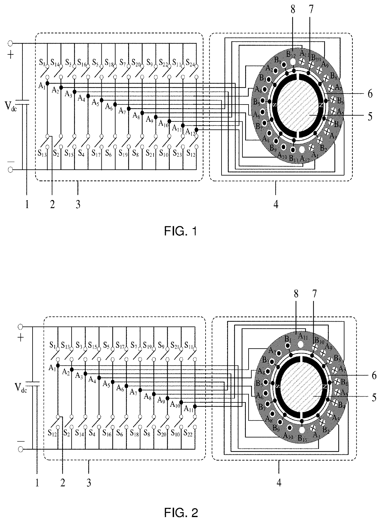
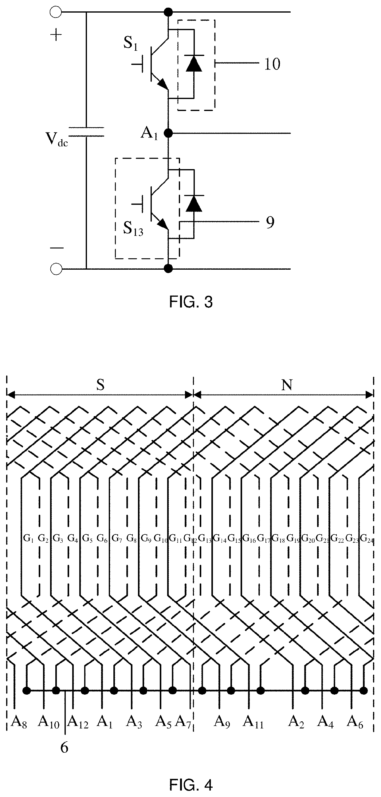
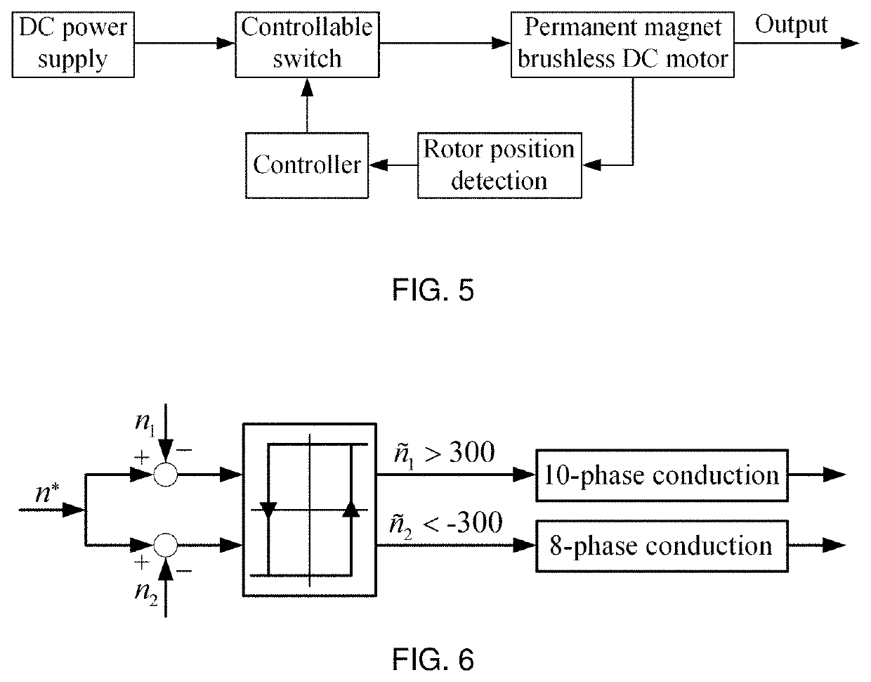
[0031]Referring to FIGS. 1-6, a control system of a flexible permanent magnet brushless DC motor comprises a DC power supply, a filter capacitor 1, a voltage source inverter 3, a permanent magnet brushless DC motor 4 and a controller. The output end of the DC power supply is connected with the filter capacitor 1 in parallel. The voltage source inverter 3 is provided with m bridge arms which are connected with both ends of the filter capacitor 1 in parallel. Upper and lower controllable switches 2 are arranged on each bridge arm, respectively. The phase number of armature winding of the permanent magnet brushless DC motor 4 is equal to the number of bridge arms. Head ends of armature windings 7 of each phase are correspondingly connected with intermediate contacts of the upper and lower cont...


PUM


Abstract

A control system of a flexible permanent magnet brushless DC motor, comprising a DC power supply, a filter capacitor, a voltage source inverter, a permanent magnet brushless DC motor and a controller, wherein an output end of the DC power supply is connected with the filter capacitor in parallel; the voltage source inverter is provided with m bridge arms which are connected with both ends of the filter capacitor in parallel; upper and lower controllable switching devices are arranged on each bridge arm; the phase number of armature winding of the permanent magnet brushless DC motor is equal to the number of bridge arms; head ends of armature windings of each phase are correspondingly connected with intermediate contacts of the upper and lower controllable switching devices of one bridge arm, tail ends of armature windings of each phase are connected together.

Description

CROSS-REFERENCE TO RELATED APPLICATIONS[0001]This Application is a national stage application of PCT / CN2020 / 094190. This application claims priorities from PCT Application No. PCT / CN2020 / 094190, filed Jun. 6, 2020, and from the Chinese patent application 202010313747.8 filed Apr. 20, 2020, the content of which are incorporated herein in the entirety by reference.TECHNICAL FIELD[0002]The present invention relates to a control system and a control method of a brushless direct current (DC) motor, in particular to a control system and a control method of a flexible permanent magnet brushless DC motor.BACKGROUND OF THE PRESENT INVENTION[0003]At present, the permanent magnet brushless DC motor replaces brush commutation of the traditional DC motor with an electronic commutation technology to retain superior performance of the DC motor, such as large starting torque, fast speed regulation response and other characteristics. It has advantages of simple structure, convenient maintenance and ...

Claims


Application Information

Patent Timeline
Patent Type & Authority Applications(United States)
IPC IPC(8): H02K5/22H02K3/28
CPCH02K5/22H02K3/28H02K2213/03H02P6/00H02P6/30H02P6/10H02P6/085
Inventor CHEN, WEIZHU, LIXIANGSHI, TINGNAXIA, CHANGLIANG
Owner TIANJIN POLYTECHNIC UNIV
Why Eureka
Try Eureka