
Liquid-cooling heat dissipation structure

Pending Publication Date: 2022-10-06
ASIA VITAL COMPONENTS SHENZHEN CO LTD
View PDF5 Cites 0 Cited by
  • Summary
  • Abstract
  • Description
  • Claims
  • Application Information

AI Technical Summary

Benefits of technology

The present invention provides a liquid-cooling heat dissipation structure for electronic components. The structure includes a substrate, a radiating fin unit, a cover body, and a stop section. The stop section is positioned between the inlet and the radiating fin unit to prevent the cooling liquid from flowing directly through the radiating fin unit. The cooling liquid flows through the periphery of the radiating fin unit and then to the middle of the radiating fin unit, which helps to evenly distribute the cooling liquid and reduce the temperature difference between the heat generation component. The structure also includes multiple flow-stopping protrusions and ribs to improve the heat exchange efficiency and prolong the retention time of the cooling liquid in the heat exchange chamber. Overall, the invention provides an effective solution for cooling electronic components.

Problems solved by technology

However, in the new-generation chip design, the heat generation area is increased so that the difference between the temperatures of the inlet and the outlet has become greater.
This leads to non-uniform temperature distribution of the chip.
The retention time of the working liquid in the water block is so short that the working liquid contacts the radiating fins in the water block is very short.
Under such circumstance, it is hard for the working liquid to fully carry away the heat by way of heat exchange.

Method used


Image

  • Liquid-cooling heat dissipation structure
  • Liquid-cooling heat dissipation structure
  • Liquid-cooling heat dissipation structure

Examples


Embodiment Construction

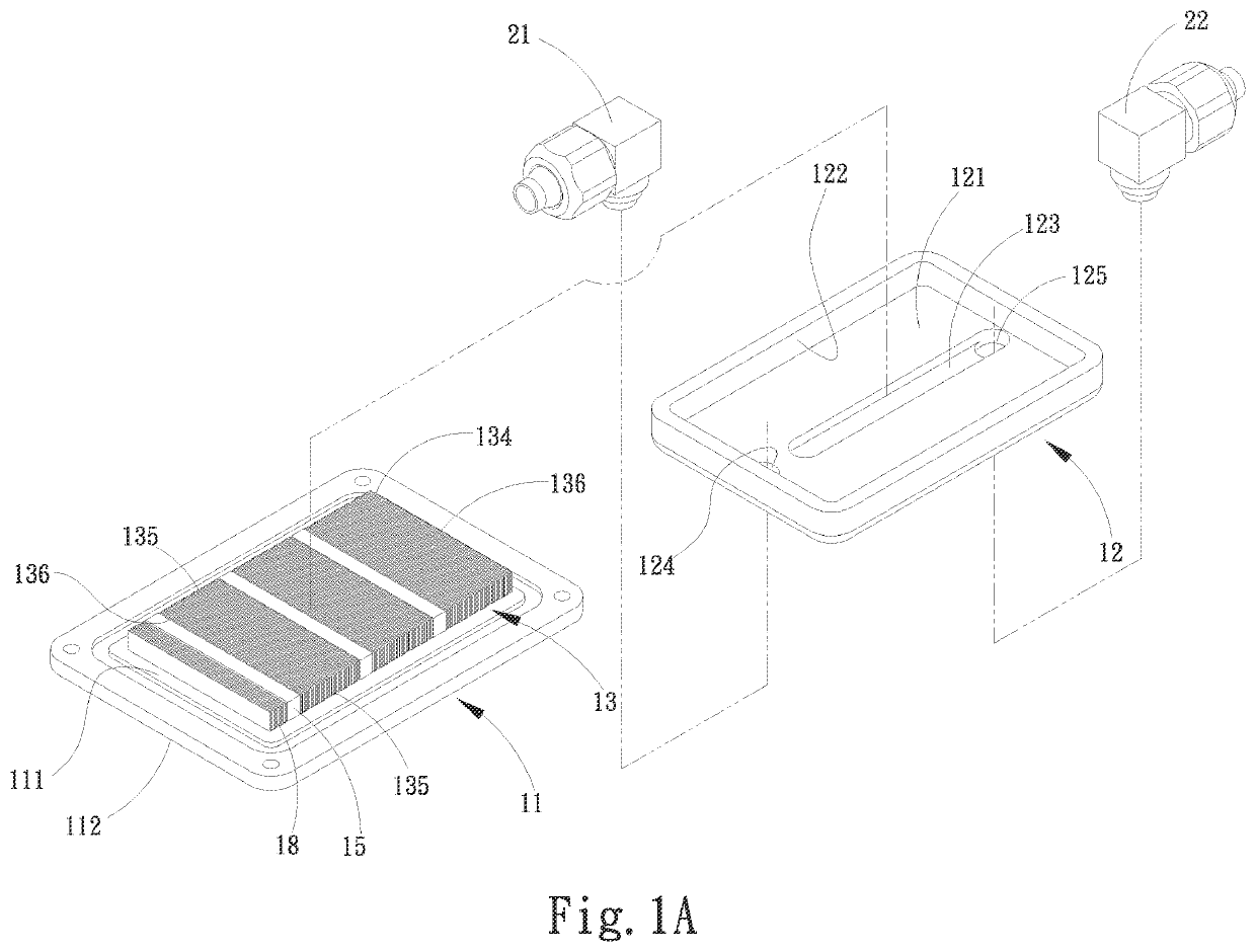
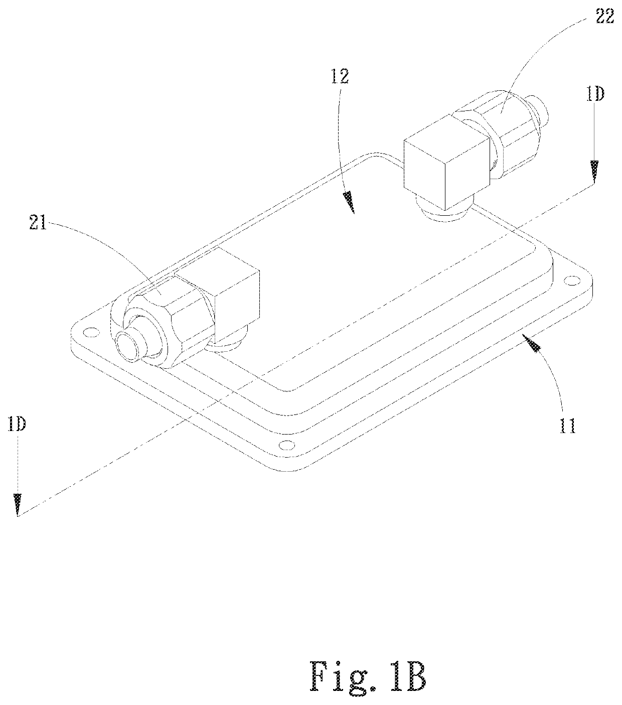
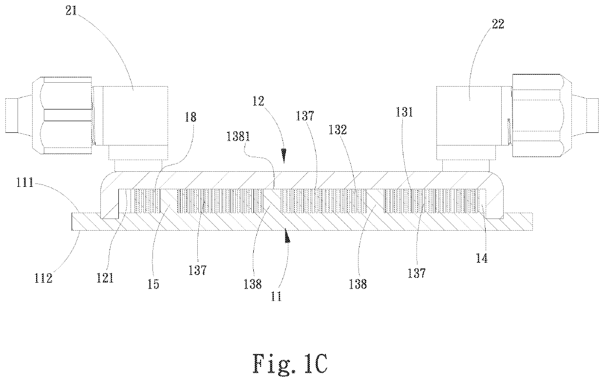
[0028]The present invention provides a liquid-cooling heat dissipation structure, for example, a liquid (water) block as a part of a liquid cooling loop. The liquid-cooling heat dissipation structure is in contact with a heat generation component to dissipate the heat of the heat generation component. The liquid-cooling heat dissipation structure is in communication with an external heat dissipation unit and / or pump via tube bodies. A stop section is disposed in a heat exchange chamber of the liquid-cooling heat dissipation structure so as to first divide the cooling liquid entering the heat exchange chamber. The divided cooling liquid flows to the periphery of a radiating fin unit and then flows to the middle of the radiating fin unit, whereby the cooling liquid is prevented from straightly passing through the radiating fin unit. Alternatively, multiple cooperative flow-stopping protrusions are disposed corresponding to the radiating fin unit to help the cooling liquid to uniformly...


PUM


Abstract

A liquid-cooling heat dissipation structure includes a substrate and a cover body mated with the substrate to define a heat exchange chamber therebetween. A radiating fin unit and a stop section are disposed in the heat exchange chamber. The stop section serves to first divide a cooling liquid entering the heat exchange chamber, whereby the cooling liquid first flows through the periphery of the radiating fin unit and then flow into the middle of the radiating fin unit so that the cooling liquid is prevented from straightly passing through the radiating fin unit. Multiple cooperative flow-stopping protrusions are disposed in the periphery of the radiating fin unit to help the cooling liquid to uniformly flow through the radiating fin unit. By means of the structural design of the liquid-cooling heat dissipation structure, the heat exchange efficiency is greatly enhanced.

Description

BACKGROUND OF THE INVENTION[0001]1. Field of the Invention[0002]The present invention relates generally to the field of liquid heat dissipation structure, and more particularly to a heat dissipation structure of a liquid (water) block.[0003]2. Description of the Related Art[0004]Along with the great enhancement of the requirement for big data and cloud computing service, the requirement for heat dissipation of related electronic products has become higher and higher. Especially, with respect to the server of a large-scale operation center, the operation density is increased so that the waste heat generated in the space with the same size is greatly increased. In order to reduce the energy consumed in heat dissipation, recently, liquid-cooling structure is employed to carry away the heat from the server and then dissipate the heat in other manner. This can solve the problem of high-density waste heat.[0005]The operation system of a water block or water plate is such that a working li...

Claims


Application Information

Patent Timeline
IPC IPC(8): F28F3/04
CPCF28F3/048F28F2250/102H05K7/20254H01L23/473F28F3/06F28F3/12F28F9/0251F28F2225/00F28F2240/00F28F2210/02F28F2210/10H01L23/3672H05K7/20772
Inventor LEE, SUNG-WEIHUANG, KUAN-LINYANG, MING-TSUNG
Owner ASIA VITAL COMPONENTS SHENZHEN CO LTD
Features
  • Generate Ideas
  • Intellectual Property
  • Life Sciences
  • Materials
  • Tech Scout
  • Unparalleled Data Quality
  • Higher Quality Content
  • 60% Fewer Hallucinations
Learn More