Method of forming a wind turbine foundation

Pending Publication Date: 2022-10-13
VESTAS WIND SYST AS
View PDF0 Cites 0 Cited by
  • Summary
  • Abstract
  • Description
  • Claims
  • Application Information

AI Technical Summary

Problems solved by technology

Firstly, the levelling apparatus forms part of the anchor cag

Method used


Image

  • Method of forming a wind turbine foundation
  • Method of forming a wind turbine foundation
  • Method of forming a wind turbine foundation

Examples


Embodiment Construction

[0034]The following detailed description refers to the accompanying drawings that show, by way of illustration, specific details and embodiments in which the invention may be practiced. These embodiments are described in sufficient detail to enable those of ordinary skill in the art to practice the invention. Other embodiments may be utilised, and structural changes may be made without departing from the scope of the invention as defined in the appended claims. As used herein, the term “level” means generally horizontal, and more particularly, generally orthogonal to the direction of gravitational force.

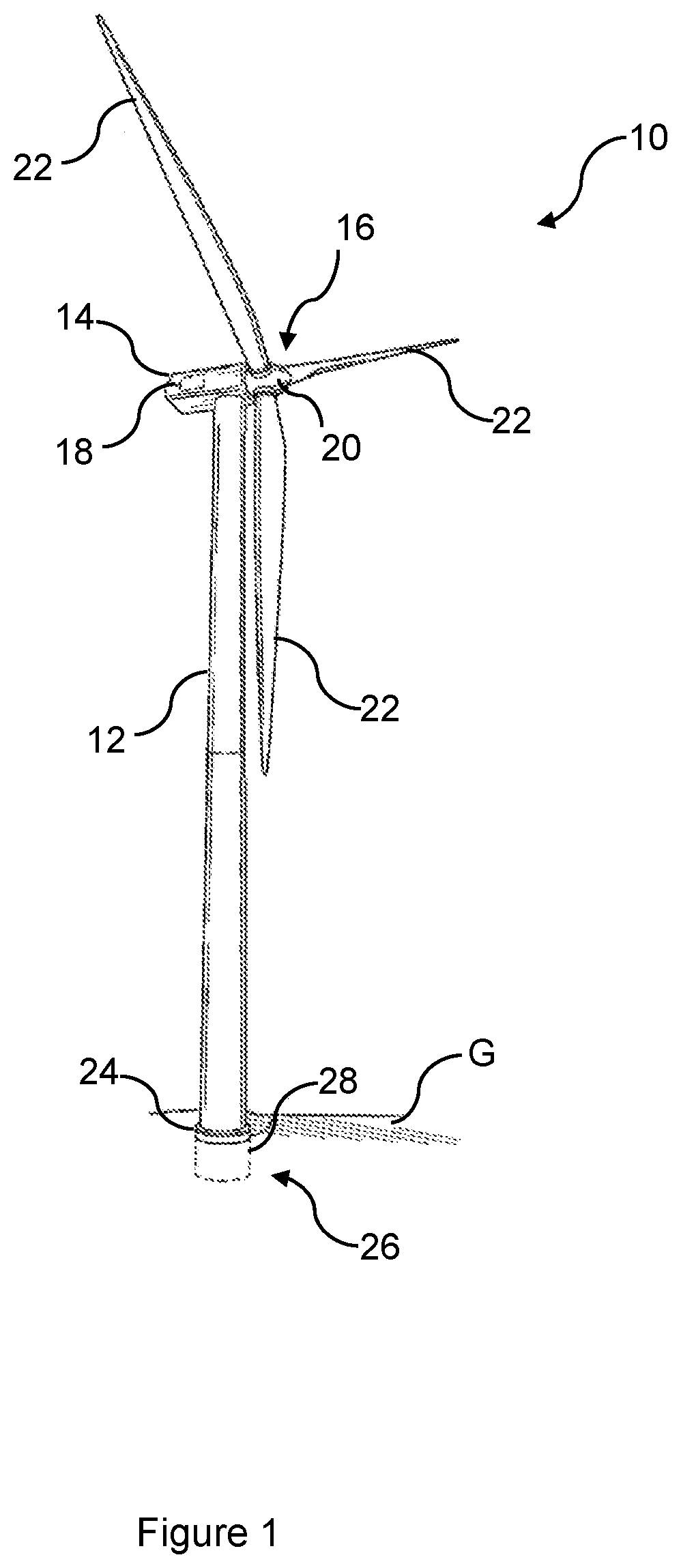
[0035]The present invention relates to a method of forming a foundation for a wind turbine generator, or more simply, wind turbine. It is desirable to provide a level mounting surface on which to install a wind turbine generator. An exemplary horizontal-axis wind turbine 10 is shown in FIG. 1, including a tower 12, a nacelle 14 disposed at the apex of the tower 12, and a rotor 16 ope...


PUM


Abstract

A method of forming a foundation (26) of a wind turbine (10) including a tower (12) having a base tower section (24), comprising: mounting a levelling apparatus (56) to an anchor cage (30), the anchor cage (30) including a plurality of anchor bolts (36) extending between an upper flange (34) and a lower flange (38), the levelling apparatus (56) being arranged between the upper and the lower flanges (34, 38); arranging the anchor cage (30) in an excavation pit (94); directing a cementitious material into the excavation pit (94) so that the upper flange (34) becomes at least partially embedded within the first cementitious material; allowing the cementitious material to cure to form a rigid body (28, 90); actuating the levelling apparatus (56) to raise the upper flange (34) from the rigid body (28, 90) into a levelled position; directing a grout material (32) into a space beneath the raised upper flange (34); and allowing the grout material (32) to cure to form a support layer. The invention extends to an anchor cage arrangement and a system for forming a wind turbine foundation.

Description

TECHNICAL FIELD[0001]Aspects of the invention relate to a method of forming a foundation of a wind turbine, and to an apparatus for forming such a wind turbine foundation.BACKGROUND[0002]Wind turbines are used to produce electrical energy by converting kinetic energy from the wind into electrical power. A horizontal-axis wind turbine generally includes a tower, a nacelle located at the apex of the tower, and a rotor having a plurality of blades and supported in the nacelle by a shaft. The shaft couples the rotor either directly or indirectly with a generator, which is housed inside the nacelle. Consequently, as wind forces the blades to rotate, electrical energy is produced by the generator.[0003]Horizontal-axis wind turbines are typically anchored on land by securing a lower portion of the tower, such as a lower tower flange, to a foundation that extends into the ground. Conventional foundations include steel-reinforced concrete structures arranged within an excavation pit. The fou...

Claims


Application Information

Patent Timeline
IPC IPC(8): E02D27/42F03D13/20
CPCE02D27/425F03D13/22E02D2300/002E02D2250/0023E02D2600/30Y02B10/30Y02E10/72Y02E10/728
Inventor DUARTE TRIGO, HUGO MIGUELATTARI, AZADEH
Owner VESTAS WIND SYST AS
Why Eureka
Try Eureka