

Coupler cap and quick coupler having the same
- Summary
- Abstract
- Description
- Claims
- Application Information
AI Technical Summary
Benefits of technology
Problems solved by technology
Method used
Image

Examples
Embodiment Construction
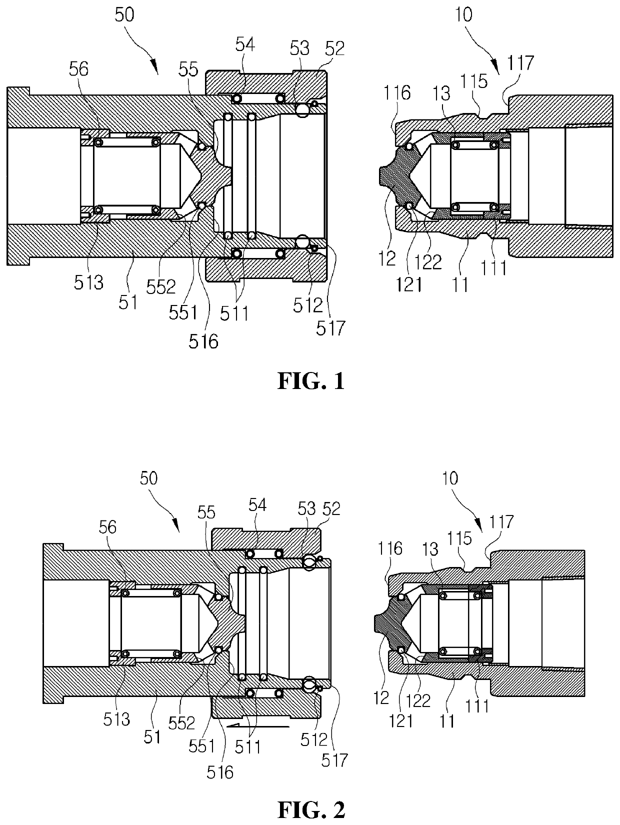
[0036]Hereinafter, a coupler cap and a quick coupler having the same according to preferred embodiments of the present invention will be described in detail with reference to the accompanying drawings. In the following description, the horizontal direction in FIG. 1 is an axial direction of the coupler, and the vertical direction in FIG. 1 is a radial direction of the coupler. Moreover, the horizontal direction in FIG. 9 is an axial direction of a cap body or a radial direction of a handle, and the vertical direction is a radial direction of the cap body or an axial direction of the handle.
[0037]Referring to FIG. 1, the quick coupler according to a preferred embodiment of the present invention is to couple and decouple a female coupler 50 and a male coupler 10 with each other and from each other. The quick coupler may be used to a pipeline, which unloads chemicals loaded in a tank truck into a storage tank of a semiconductor manufacturing factory.
[0038]The female coupler 50 includes...
PUM
 Abstract
Description
Claims
Application Information