Compact Low-power Cryo-Cooling Systems for Superconducting Elements

a superconducting element, low-power technology, applied in the direction of gas cycle refrigeration machines, refrigeration machines, lighting and heating apparatus, etc., can solve the problem of lower thermodynamic efficiency than those coolers, and achieve the effect of minimizing the effect of secondary flows

Pending Publication Date: 2022-11-03
UNIV OF COLORADO THE REGENTS OF +1
View PDF0 Cites 0 Cited by
  • Summary
  • Abstract
  • Description
  • Claims
  • Application Information

AI Technical Summary

Benefits of technology

[0012]Preferred embodiments utilize geometries that minimize the

Problems solved by technology

Although a He JT would reach temperatures approaching 1 K, He was selected for the initial development because of the relative high cost and rarity of He.
Preferred embod

Method used


Image

  • Compact Low-power Cryo-Cooling Systems for Superconducting Elements
  • Compact Low-power Cryo-Cooling Systems for Superconducting Elements
  • Compact Low-power Cryo-Cooling Systems for Superconducting Elements

Examples


Embodiment Construction

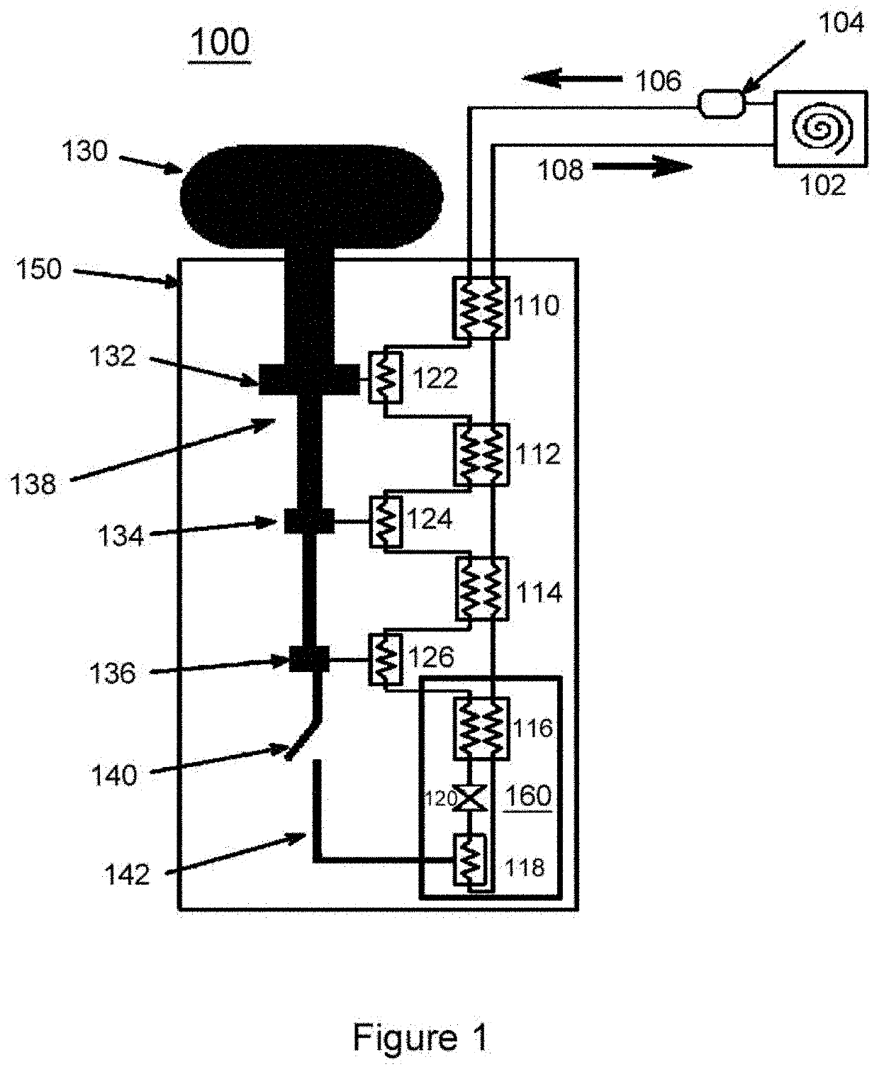
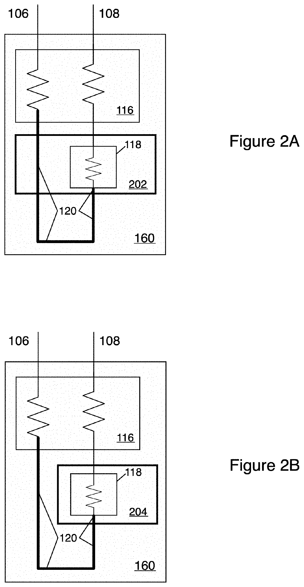
[0019]FIG. 1 is a schematic block diagram of the present cooler system 100. System 100 is a compact cooler having a form factor and low power draw of a standard rack-mountable electronics instrument. The cooler is a pulse tube / Joule-Thomson (PT / JT) hybrid, with the JT stage 160 achieving 1.4 mW of cooling at 1.7 K or 2.2K (depending on the configuration, see FIGS. 2A and 2B), and the three-stage 132, 134, 136 pulse tube 138 providing cooling at 80 K (132), 25 K (134), and 10 K (136).

[0020]System 100 comprises a cryo-cooler compressor 102 providing high-pressure gas out 106 and low-pressure gas in 108 and includes a filter 104. Pulse tube cooler 130 includes an 80K stage 132, a 25K stage 134, and a 10K stage 136 housed within vacuum shell 150. Also within vacuum shell 150 are thermal busbar 142, heat exchangers 122, 124, 126, and 118, as well as counterflow heat exchangers 110, 112, 114, and 116. Counterflow heat exchanger 116 and heat exchanger 118 are part of JT stage 160, as is JT...


PUM


Abstract

A compact, low power cryo-cooler for cryogenic systems capable of cooling gas to at least as low as 2.5 K. The cryo-cooler has a room temperature compressor followed by filtration. Within the cryostat, four counterflow heat exchangers precool the incoming high-pressure gas using the outflowing low-pressure gas. The three warmest heat exchangers are successively heat sunk to three stages of a pulse tube to absorb residual heat from the slight ineffectiveness of the heat exchangers. The pulse tube cold head also absorbs loads from instrumentation leads and radiation loads. The pulse tube stages operate at around 80 K, 25 K, and 10 K. The entire system—cryo-cooler, drive and control electronics, and detector instrumentation, fits in a standard electronics rack mount enclosure, and requires around 300 W or less of power.

Description

BACKGROUND OF THE INVENTION[0001]This application incorporates by reference parent applications 62 / 621,483, filed Jan. 24, 2018, and 16 / 256,736, filed Jul. 24, 2019.[0002]This invention was made with government support under grant number 70NANB14H095 awarded by NIST. The government has certain rights in the invention.FIELD OF THE INVENTION[0003]The present invention relates to compact, low-power cryo-cooling systems for superconducting elements. In particular, the present invention relates to such systems having a pulse tube compressor and a Joule-Thomson (JT) cooler.[0004]DISCUSSION OF RELATED ART[0005]Applications for superconductor-based sensors and electronics have been steadily increasing over the past several years in diverse areas such as astrophysics / cosmology, X-ray spectroscopy, gamma-ray spectroscopy, quantum information, and photon science. These systems operate at temperatures ranging from above 4 K to lower than 50 mK. Although these systems are developed by scientists...

Claims


Application Information

Patent Timeline
IPC IPC(8): F25B9/02F25B9/14F25B9/10
CPCF25B9/02F25B9/145F25B9/10F25B2309/02
Inventor KOTSUBO, VINCENTULLOM, JOELNAM, SAE WOO
Owner UNIV OF COLORADO THE REGENTS OF
Why Eureka
Try Eureka