Control device and control method for internal combustion engine

a control device and control method technology, applied in the direction of electric control, ignition automatic control, machines/engines, etc., can solve the problems of reducing the combustion performance of the main combustion chamber, reducing the combustion performance of the pre-combustion chamber, and limiting the use of only hardware measures, so as to suppress the reduction of combustion performance and efficiently exhausted

Active Publication Date: 2022-11-17
MITSUBISHI ELECTRIC CORP
View PDF18 Cites 0 Cited by
  • Summary
  • Abstract
  • Description
  • Claims
  • Application Information

AI Technical Summary

Benefits of technology

[0008]In the control device and the control method for the internal combustion engine according to the present disclosure, burnt gas and the like staying in the pre-combustion chamber can be efficie

Problems solved by technology

In the pre-chamber type engine, since the pre-combustion chamber is connected to the main combustion chamber via the orifice, there is a problem with scavenging performance, so that the burnt gas generated through combustion is likely to stay in the pre-combustion chamber.
Due to staying of the burnt gas, a necessary amount of fuel cannot enter the inside of the pre-combustion chamber, so that combustion in the pre-combustion chamber is weakened.
As a result, combustion flame jetted from the pre-combustio

Method used


Image

  • Control device and control method for internal combustion engine
  • Control device and control method for internal combustion engine
  • Control device and control method for internal combustion engine

Examples


first embodiment

[0019]Hereinafter, an internal combustion engine (engine) according to the first embodiment of the present disclosure will be described with reference to the drawings.

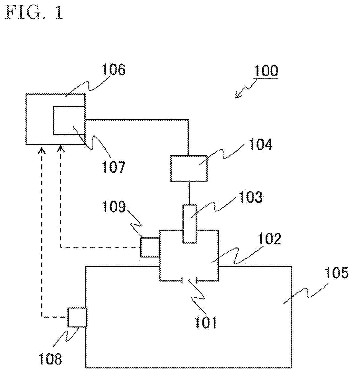
[0020]FIG. 1 is a schematic configuration diagram of the internal combustion engine according to the first embodiment. In FIG. 1, an internal combustion engine 100 includes: a main combustion chamber 105; a pre-combustion chamber 102 having, between the pre-combustion chamber 102 and the main combustion chamber 105, at least one orifice 101 communicating with the main combustion chamber 105; a spark plug 103 which is located in the pre-combustion chamber 102 and has an electrode (not shown), and which generates spark discharge between the electrode and a ground electrode by high voltage applied; an ignition coil 104 for providing high voltage to the spark plug 103; a first control device 106 which controls operation of the ignition coil 104 to generate spark discharge at the spark plug 103; and a second control device ...


PUM


Abstract

An object is to improve scavenging performance of a pre-combustion chamber connected to a main combustion chamber via an orifice and suppress reduction in combustion performance of an internal combustion engine. This control device for an internal combustion engine including a main combustion chamber and a pre-combustion chamber having at least one orifice between the pre-combustion chamber and the main combustion chamber, includes a first control device which controls operation of an ignition coil to generate spark discharge at a spark plug, thus combusting fuel gas, and a second control device which controls operation of the ignition coil at a timing other than the timing of combusting the fuel gas, to promote scavenging of the pre-combustion chamber.

Description

BACKGROUND OF THE INVENTION1. Field of the Invention[0001]The present disclosure relates to a control device and a control method for an internal combustion engine.2. Description of the Background Art[0002]For addressing global warming having been raised as an issue in recent years, approaches to reduce greenhouse gases have begun worldwide. Also in the automobile industry, this issue needs to be addressed, and development is going on for improving efficiency of an internal combustion engine. As an example of configurations for improving efficiency of an internal combustion engine, there is a configuration called a pre-chamber type engine in which a pre-combustion chamber having an orifice is provided ahead of a spark plug, fuel in the pre-combustion chamber is ignited, and combustion flame is jetted from the orifice to a main combustion chamber, to ignite fuel in the main combustion chamber (see, for example, Patent Document 1). In this configuration, the fuel in the main combustio...

Claims


Application Information

Patent Timeline
IPC IPC(8): F02B19/12F02B19/18F02P5/15F02B29/00
CPCF02B19/12F02B19/18F02P5/1502F02B29/00Y02T10/12F02P3/04F02P15/08F02P5/045F02D35/025F02D37/02F02D41/009
Inventor TANAYA, KIMIHIKO
Owner MITSUBISHI ELECTRIC CORP
Why Eureka
Try Eureka