Tire abnormality sensor

a technology of abnormality sensor and tire, which is applied in the direction of digital computer details, instruments, transportation and packaging, etc., can solve the problem of not constant pulse signals

Inactive Publication Date: 2000-01-11
DENSO CORP
View PDF7 Cites 21 Cited by
  • Summary
  • Abstract
  • Description
  • Claims
  • Application Information

AI Technical Summary

Problems solved by technology

However, the pulse signals are not constant due to nonstandard factors such as manufacturing error, corrosion, deformation during drive or the like of the signal rotor.

Method used


Image

  • Tire abnormality sensor
  • Tire abnormality sensor
  • Tire abnormality sensor

Examples


first embodiment

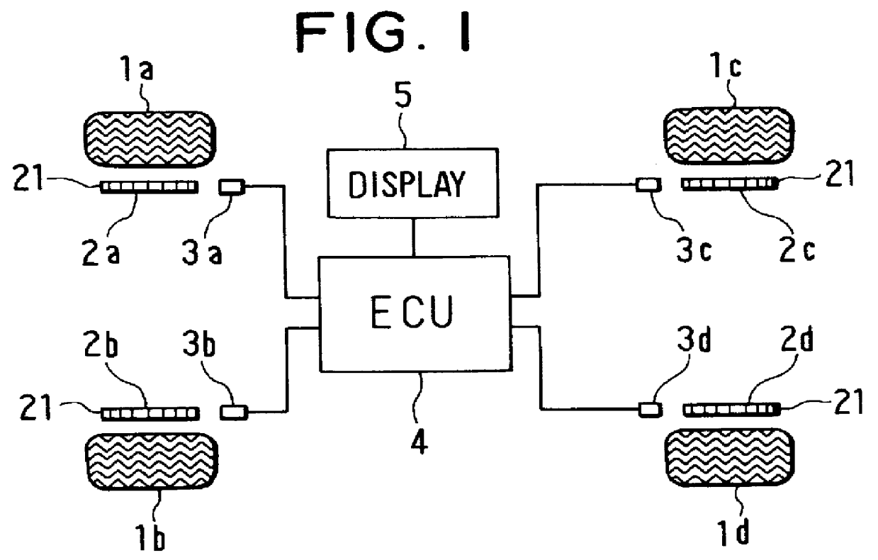
FIG. 1 shows a tire abnormality sensor according to a first preferred embodiment of the present invention. The tire abnormality sensor includes vehicle tires 1a-1d; signal rotors 2a-2d as rotors which rotate in unison with the tires; and electromagnetic pickups 3a-3d as rotation sensing devices provided at positions near the outer circumferences of the signal rotors 2a-2d, respectively. Each of the signal rotors 2a-2d is a toothed wheel on which a number (48 in the embodiment) of teeth 21 made of a magnetic material are formed in the circumferential direction thereof at equal intervals. The teeth 21 function as rotation sensors 21. The electromagnetic pickups 3a-3d sense a change in the magnetic field which is associated with passage of each of the teeth of the signal rotors 2a-2d which rotate integrally with the tires 1a-1d, and, for example, each time one of the teeth passes, one sensor signal in a sine wave shape is generated. The sensor signal regarding each of the signal rotor...

second embodiment

A wheel speed sensor according to a second preferred embodiment of the present invention has a construction substantially the same as that shown in FIG. 1. Mainly the software executed by the microprocessor in the ECU 4 and the like are different. In those Figures, since substantially the same operations are performed with respect to steps designated by the same numbers as those in FIGS. 3 and 6-8 which were referred to in the description of the first embodiment, the different points from the first embodiment will be mainly described here.

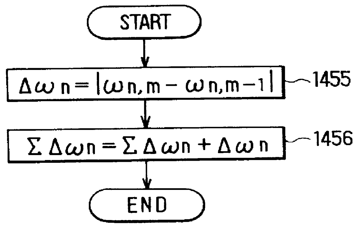
In step 1450A after calculating the correction coefficient (corresponding to step 1440 in FIG. 6), as shown in FIG. 11, an aging change amount .DELTA..omega..sub.n of the correction coefficient is calculated according to Equation (9) (step 1455).

.DELTA..omega..sub.n =.vertline..omega..sub.n,m -.omega..sub.n,m-1 .vertline. (9)

In the following step 1456, the aging change amount .DELTA..omega..sub.n calculated in step 1455 is added to an integrated va...

third embodiment

In a wheel speed sensor according to a third preferred embodiment of the present invention, the construction and the speed pulse interrupting process are basically the same as those of the second embodiment, but another periodic interrupting process is performed in place of the periodic interrupting process of the second embodiment. FIG. 13 shows a flow of the periodic interrupting process of the embodiment. In the diagram, with respect to steps designated by the same numbers as those in FIG. 12 which were referred to in the description of the first and second embodiments, substantially the same operations are performed. Points different from the second embodiment will be mainly described.

In FIG. 13, whether an initializing operation is executed or not is discriminated in step 3070. The initializing operation is a switch operation performed by a driver or the like and is executed at the tire normal state such as at the time of tire replacement. If the initializing operation has been...


PUM


Abstract

To achieve both accuracy in correcting sensing error caused by nonstandard factors of a pulse signal generated by rotation of a rotor to be measured and reduction in cost of an apparatus for doing the same, each passage of rotor sensors which rotate integrally with vehicle tires are sensed to produce pulse signals. The pulse signal periods are sequentially integrated every pulse signal train consisting of multiple pulse signals. When all of the pulse signal periods of the pulse signal train are integrated, the integrated value is stored in memory. The memory always stores the integrated values of the newest one rotation of the rotor to be measured. The pulse signal periods are averaged from the sum of the integrated values. With such a construction, the average of the pulse signal periods can be obtained as a learning reference value in the correction without storing all of the pulse signal periods of one rotation, thereby realizing both correction accuracy and cost reduction.

Description

This application is related to Japanese Patent Application Nos. Hei 8-248999 and 8-249000, incorporated herein by reference.1. Field of the InventionThe present invention relates to a tire abnormality sensor for sensing abnormality of tires of a vehicle.2. Description of Related ArtA tire abnormality sensor is an apparatus for monitoring the state of tires during drive, sensing abnormality such as deflation, and notifying a driver or the like of the abnormality. As a technique of sensing the tire state, other than a conventionally-known technique of sensing tire pressure or temperature in a tire, there is a technique in which attention is paid to the fact that the tire radius is changed when the tire is deflated, and an angular velocity of a wheel is sensed. As a method using such a technique of sensing the tire state, Japanese Patent Laid-Open Publication No. Hei 4-232107 discloses a method of sensing the deflation of a tire by calculating a linear function of the difference betwee...

Claims


Application Information

Patent Timeline
Patent Type & Authority Patents(United States)
IPC IPC(8): B60C23/06
CPCB60C23/061
Inventor INOUE, YUICHITAGUCHI, TAKEYASU
Owner DENSO CORP
Why Eureka
Try Eureka