Wind turbine

Inactive Publication Date: 2000-01-18
TERRA MOYA AQUA
View PDF9 Cites 97 Cited by
  • Summary
  • Abstract
  • Description
  • Claims
  • Application Information

AI Technical Summary

Benefits of technology

The present invention also provides a pyramid base for supporting the wind turbine apparatus and for enclosing the electrical generator, control system, batteries, etc. The base has sloping walls to direct wind currents upwardly toward the rotor. This results in additional efficiency of the apparatus.
In another aspect, the present invention provides uniquely shaped rotor blades in which the outer edge

Problems solved by technology

However, such machines cannot be safely operated in high wind conditions because they lack sufficient structural integrity.
Furthermore, such machines are deadly to any birds which may fly

Method used


Image

  • Wind turbine
  • Wind turbine
  • Wind turbine

Examples


Embodiment Construction

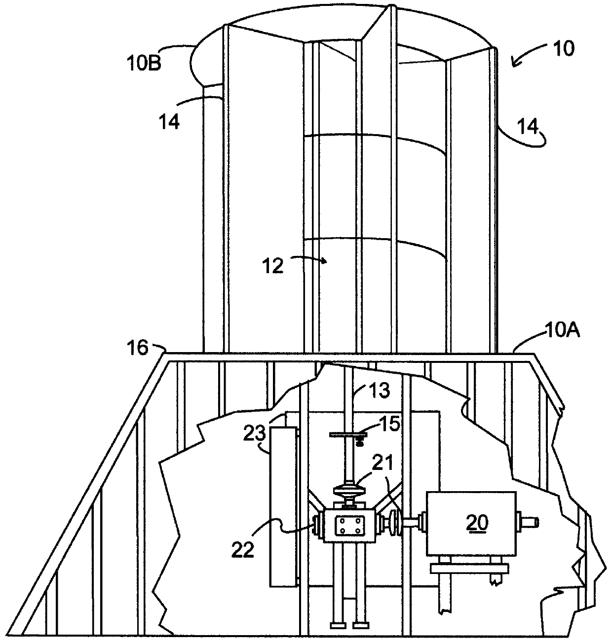
In the accompanying drawings there is shown one embodiment of wind turbine apparatus 10 of the invention which comprises a rotatable rotor 12 and a plurality of stationary or fixed airfoils 14 which are positioned around the perimeter of the rotor 12. Preferably a top plate 10B is secured to the upper ends of the airfoils, and a bottom plate 10A is secured to the lower ends of the airfoils to improve structural strength and to force wind currents which enter the apparatus to push against the rotor blades.

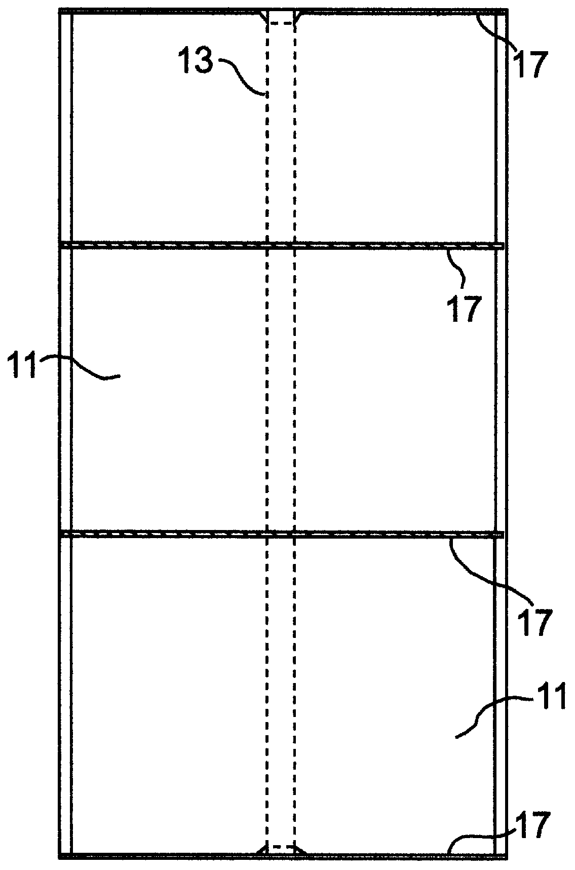
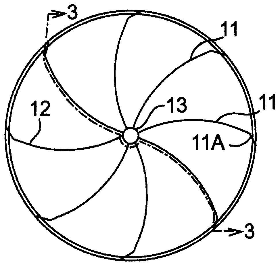
The rotor includes a plurality of blades 11 which radiate outwardly from a central shaft 13. The rotor blades are preferably all of the same size and style and are equidistantly spaced around the central shaft. The preferred shape of the blades is as shown in FIG. 2. The portion 11A along the outer edge of each blade is angled away from the direction of rotation of the rotor (e.g. about 15 to 80 degrees). The blades are concave on the side which is acted upon by the wind currents. T...


PUM


Abstract

Wind turbine apparatus is described for converting wind energy into electrical energy. The apparatus includes a rotatable central shaft, a plurality of rotor blades attached to the central shaft, and a plurality of convex airfoils spaced around the periphery of the rotor blades. The ratio of the number of rotor blades to the number of airfoils is at least 1.25 to 1. The size of the apparatus may vary, and the apparatus is useful in a variety of applications and environments. It is very efficient in converting wind energy to electrical energy. It may be operated even in very high wind conditions.

Description

FIELD OF THE INVENTIONThis invention relates to wind-driven turbines which are capable of generating electrical energy. More particularly, this invention relates to wind turbines of the type having a rotor and a plurality of stationary stators positioned around the rotor.BACKGROUND OF THE INVENTIONWindmills and wind turbine machines of various designs have been previously proposed for use in converting wind energy to electrical energy. Machines of the type utilizing a plurality of exposed blades rotating about a horizontal axis are in commercial use in a number of different locations. However, such machines cannot be safely operated in high wind conditions because they lack sufficient structural integrity. Furthermore, such machines are deadly to any birds which may fly into the path of the rotating blades.Previously disclosed wind turbines typically utilize a rotor which is rotatable about a vertical axis. The rotor normally includes a plurality of blades. A plurality of stationary...

Claims


Application Information

Patent Timeline
IPC IPC(8): F03D3/06F03D3/04F03D3/00
CPCF03D3/0409F03D3/061Y10S416/06Y10S415/907Y02E10/74Y02E10/728F03D13/20F03D9/25
Inventor TAYLOR, RONALD J.
Owner TERRA MOYA AQUA
Why Eureka
Try Eureka