Rotary turbomachine having a transonic compressor stage

Inactive Publication Date: 2000-01-25
MOTOREN UND TURBINEN UNION MUNCHEN GMBH
View PDF9 Cites 197 Cited by
  • Summary
  • Abstract
  • Description
  • Claims
  • Application Information

AI Technical Summary

Problems solved by technology

In rotary turbomachines having a compressor stage operating in the transonic region, the problem has been recognized that an excessive Mach number of the fluid flow arises on the suction side of the compressor blades, especially in the vicinity of the hub and/or the housing, due to the finite thickness of the compressor blades, and the consequent effect on the flow conditions.
As a result, the danger of boundary layer separation arises on the suction sides of the blades.
Problems would arise if one would attempt to apply the concepts of the above mentioned surface area rule to the construction of the compressor stage of a turbine engine or other rotary turbomachine.
Such a supersonic nozzle would consequently lead to an undesirable increase of the Mach number of the airflow at these locations.
Namely, while such an increase in surface area leads to an improved flow condition under subsonic

Method used


Image

  • Rotary turbomachine having a transonic compressor stage
  • Rotary turbomachine having a transonic compressor stage
  • Rotary turbomachine having a transonic compressor stage

Examples


Example

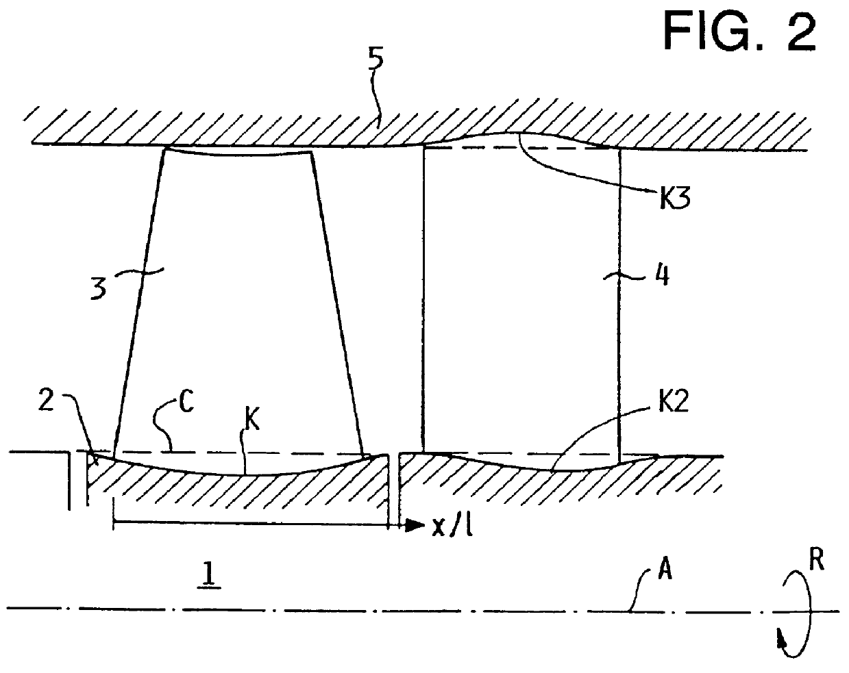
FIG. 2 is a simplified schematic illustration of an axial section through a portion, and specifically a compressor stage, of a turbojet engine, which may be used for propelling a high power or high capacity aircraft, for example. The compressor stage of the jet engine includes a rotor disk 1 and a stator 4 arranged in a housing 5. The rotor disk 1 includes a hub 2 and a plurality of compressor blades 3 extending radially from the hub 2, whereby each of the compressor blades 3 has an aerodynamic profile. A plurality of stator blades 4 extend radially between and are connected to a non-rotating stator hub and the non-rotating housing 5. As the rotor 1 rotates about its axis A in the rotation direction R, a flow of air is compressed and caused to flow toward the right in FIG. 2 due to the pressure difference between the pressure side and the suction side of each one of the compressor blades 3, which is caused by the respective aerodynamic profile and arrangement thereof. FIG. 2 further...


PUM


Abstract

A rotary turbomachine, and particularly a turbojet engine, has a compressor stage that is especially adapted for operation in the transonic region. The compressor stage includes a rotor (1) having a hub (2) and a plurality of compressor blades (3) extending radially therefrom, and a stator having a plurality of compressor blades extending radially between a stator hub and a housing. The hub (2) of the rotor (1), and/or the hub of the stator, and/or the housing of the stator, have a circumferential surface contour that is not continuously rotationally symmetrical. Namely, a concave contour (K) is provided in the circumferential surface of the hub near the base of each blade (3) on the pressure side (PS) thereof, while the circumferential surface on the suction side (SS) of the base of each blade has a contour that is linear, slightly convex, convex/concave, or slightly concave to a lesser degree than the concave contour (K) on the pressure side of each blade. The hub contour slopes and transitions smoothly radially outwardly from the concave contour (K) on the pressure side to the flatter or convex contour on the suction side. In this manner, fluid flow velocities on both the pressure side and the suction side of each blade are reduced, especially under transonic operating conditions, and compression shock losses can be minimized.

Description

PRIORITY CLAIMThis application is based on and claims the priority under 35 U.S.C. .sctn.119 of German Patent Application 196 50 656.5-13, filed on Dec. 6, 1996. The entire disclosure of German Patent Application 196 50 656.5-13 is incorporated herein by reference.The invention relates to a rotary turbomachine, and more particularly a gas turbine machine and especially a turbojet engine, having a compressor stage that operates in the transonic region and that includes a rotor comprising a hub and a plurality of compressor blades extending radially from the hub, and / or a stator comprising a hub, a housing, and a plurality of compressor blades extending radially between the hub and the housing.BACKGROUND INFORMATIONIn rotary turbomachines having a compressor stage operating in the transonic region, the problem has been recognized that an excessive Mach number of the fluid flow arises on the suction side of the compressor blades, especially in the vicinity of the hub and / or the housing...

Claims


Application Information

Patent Timeline
IPC IPC(8): F01D5/14F04D21/00F04D29/66F04D29/68F04D29/40F04D29/54F04D29/32
CPCF01D5/143F04D21/00F04D29/321F04D29/542F04D29/681Y02T50/673Y10S415/914F04D29/544Y02T50/60
Inventor HOEGER, MARTINSCHMIDT-EISENLOHR, UWE
Owner MOTOREN UND TURBINEN UNION MUNCHEN GMBH
Why Eureka
Try Eureka