Electrowinning cell

a technology of electrolyte and cell, which is applied in the direction of electrolyte, diaphragm, electrical-based machining apparatus, etc., can solve the problems of increasing the cost of gold recovery, restricting the flow of electrolyte, and reducing the efficiency of electrolyte recovery

Inactive Publication Date: 2000-01-25
F L SMIDTH & CO AS
View PDF6 Cites 23 Cited by
  • Summary
  • Abstract
  • Description
  • Claims
  • Application Information

AI Technical Summary

Problems solved by technology

This periodic procedure slows the gold recovery process, and increases its cost.
Such build-up tends to reduce voidage, restricting electrolyte flow and reducing cell efficiency.
The spacing of the electrodes is often limited by the danger of the cathode deposit reaching the anode during operation.

Method used


Image

  • Electrowinning cell
  • Electrowinning cell
  • Electrowinning cell

Examples


Embodiment Construction

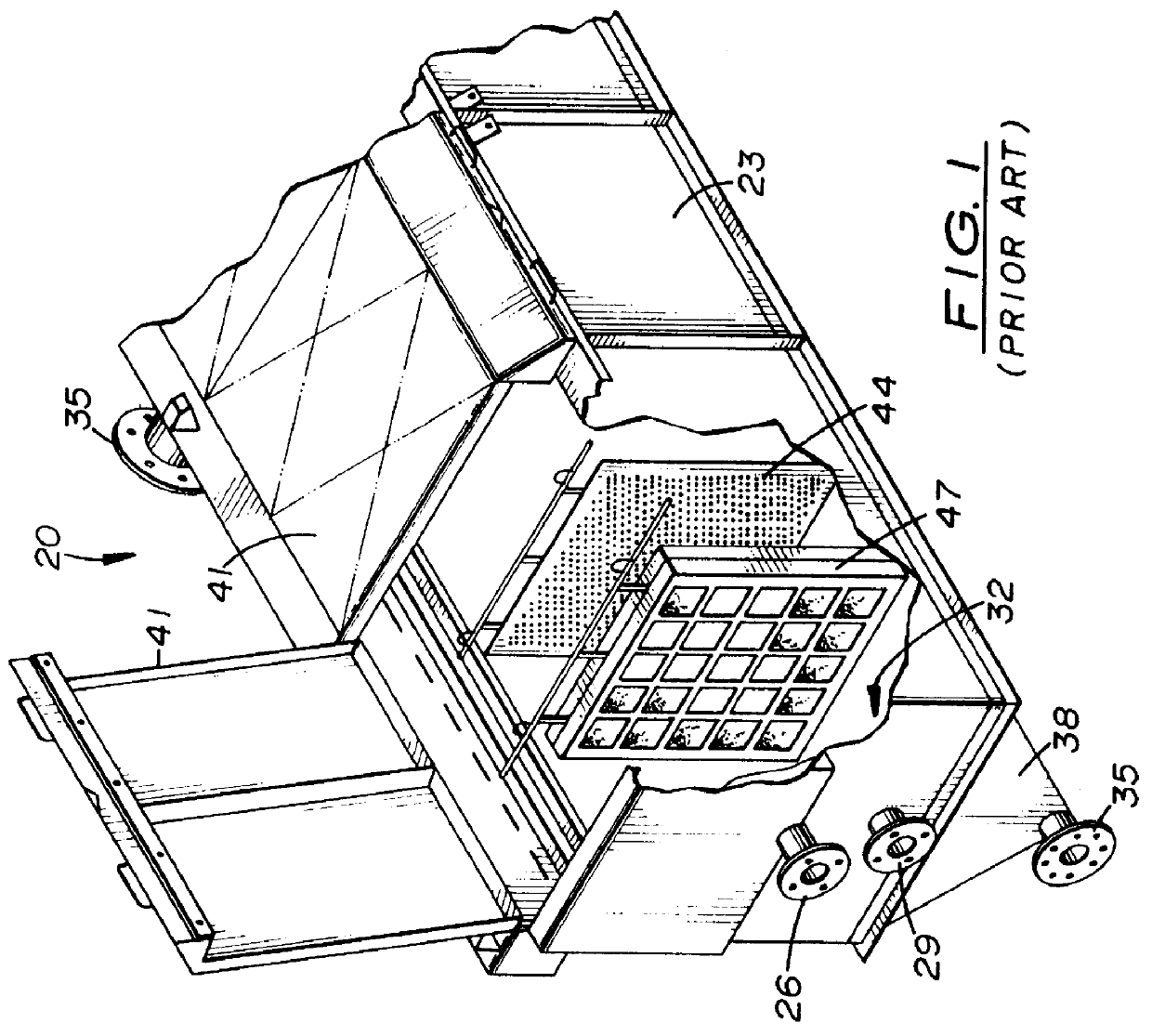
An electrolytic cell assembly 20 (FIG. 1) called an electrowinning cell, comprises a cell body 23, an inlet 26 for, typically, a caustic cyanide-water solution (not shown) of high grade gold, silver, or other dissolved metals. Body 23 also carries a solution decanting outlet 29, a sludge collection area 32, and an outlet 35 for sludge containing elemental gold from the bottom 38 of cell 20. This sludge needs only to be washed and filtered to obtain elemental gold, of a purity determined by the gold ore. Evolved gases are removed through outlet 35 during the electrowinning process. Lids 41 close cell body 23 tightly latched against seals, not shown. Anodes 44 and cathodes 47 are suspended within the ore solution within cell body 23, in the general location shown in FIG. 1. More representative actual cathode / anode spacings are shown in FIG. 6. Electrical bus bars are provided for applying voltage D.C. to the anodes 44, and to conduct induced voltage from the cathodes 47 away. Not show...


PUM

PropertyMeasurementUnit
diameteraaaaaaaaaa
metallicaaaaaaaaaa
conductivityaaaaaaaaaa

Abstract

An electrowinning cell and a cathode for use therein for removal of gold or other precious metals from a solution thereof in a suitable electrolyte. The cathode comprises a perforated steel plate wrapped in layers of woven wire mesh secured thereto. The cathode design is such that the cathode may be cleared of deposited gold sludge by use of an ordinary garden hose spray nozzle without its removal from the cell, making the electrowinning process faster and more economical.

Description

1. FieldThe field of the invention is electrolytic recovery of gold from solutions thereof, more particularly to treat carbon eluates and the like to deposit gold-bearing sludges for further refining upon cathode assemblies.2. Prior ArtPrior art electrowinning, for cathodic production of gold, generally involves the displacement of gold from an aqueous alkaline cyanide solution in an electrolytic cell carrying alternately spaced anodes and cathodes. At proper voltage, deposition of the metal starts upon the cathodes, at a rate depending upon solution parameters, such as conductivity, concentration of ionic species present, temperature and applied cell current. The source of the deposited gold is ionic gold-cyanide within the caustic solution. When parameters are favorable, a fluffy, porous deposit of elemental gold forms upon the cathode, and in some instances then falls upon the cell floor. Other conditions may produce plating upon the cathode, which may be acceptable with some app...

Claims


Application Information

Patent Timeline
Patent Type & Authority Patents(United States)
IPC IPC(8): C25C7/02C25C7/00
CPCC25C7/02
Inventor HILL, ELDAN L.GALE, CHARLES O.
Owner F L SMIDTH & CO AS
Why Eureka
Try Eureka