Exhaust manifold of multi-cylinder internal combustion engine

a multi-cylinder internal combustion engine and exhaust manifold technology, which is applied in the direction of machines/engines, other domestic objects, branching pipes, etc., can solve the problems of unnecessarily thick double half wall portion, delay in activation of catalyst, and increase useless weight, so as to avoid exhaust interference, maintain the strength and rigidity necessary for the exhaust manifold, and improve the effect of space efficiency

Inactive Publication Date: 2000-02-01
HONDA MOTOR CO LTD
View PDF6 Cites 41 Cited by
  • Summary
  • Abstract
  • Description
  • Claims
  • Application Information

AI Technical Summary

Benefits of technology

According to the above exhaust manifold, layout of good space efficiency, lightening of the exhaust manifold and early activation of the catalyst are possible, while avoiding exhaust interference.
By making the partition body thicker than any of the obverse half body and the reverse half body, it is possible to make average wall thickness of the whole exhaust manifold thin for lightening while strength and rigidity necessary for the exhaust manifold are maintained.
A silencer may be arranged on reverse side surfaces of the partition body and the reverse half body and a communication hole communicating with the sile

Problems solved by technology

Since sufficient strength and rigidity are ensured by the single wall, the doubled half wall portion is unnecessarily thick only to increase the weight uselessly.
An exhaust manifold having appropriate wall thickness as a whole can not be formed, the

Method used


Image

  • Exhaust manifold of multi-cylinder internal combustion engine
  • Exhaust manifold of multi-cylinder internal combustion engine
  • Exhaust manifold of multi-cylinder internal combustion engine

Examples


Embodiment Construction

Referring now to FIGS. 1 to 11, one preferred embodiment of the present invention will be described.

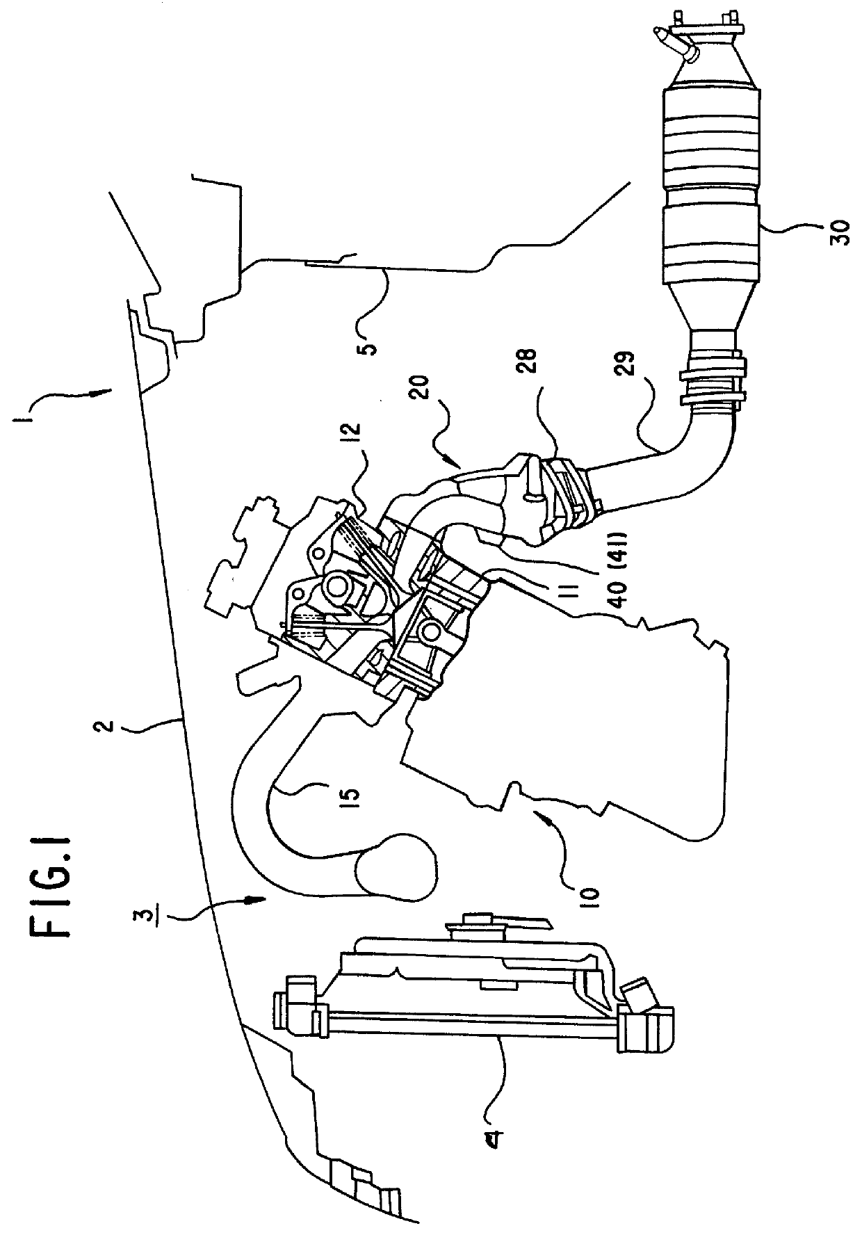
A motorcar 1 in the embodiment is a FF (front engine--front drive) car and FIG. 1 is a rough side view showing an internal combustion engine 10 arranged in a front part of the motorcar 1.

Within an engine compartment 3 under a bonnet 2 and between a radiator 4 in front and a dashboard 5 in rear is mounted a straight type 4 cylinders internal combustion engine 10 with a crankshaft directed laterally and cylinder block 11 inclined rearward.

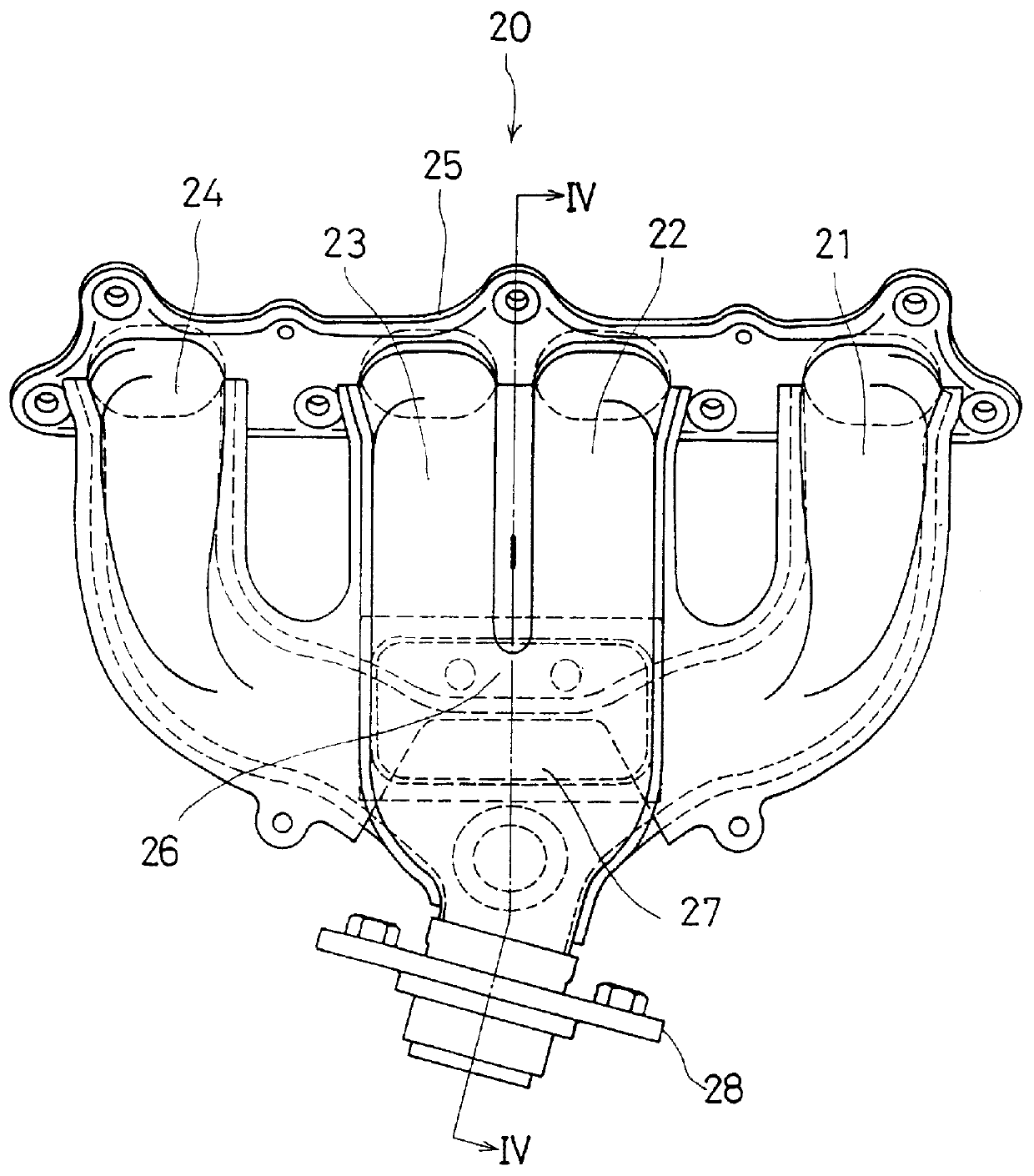
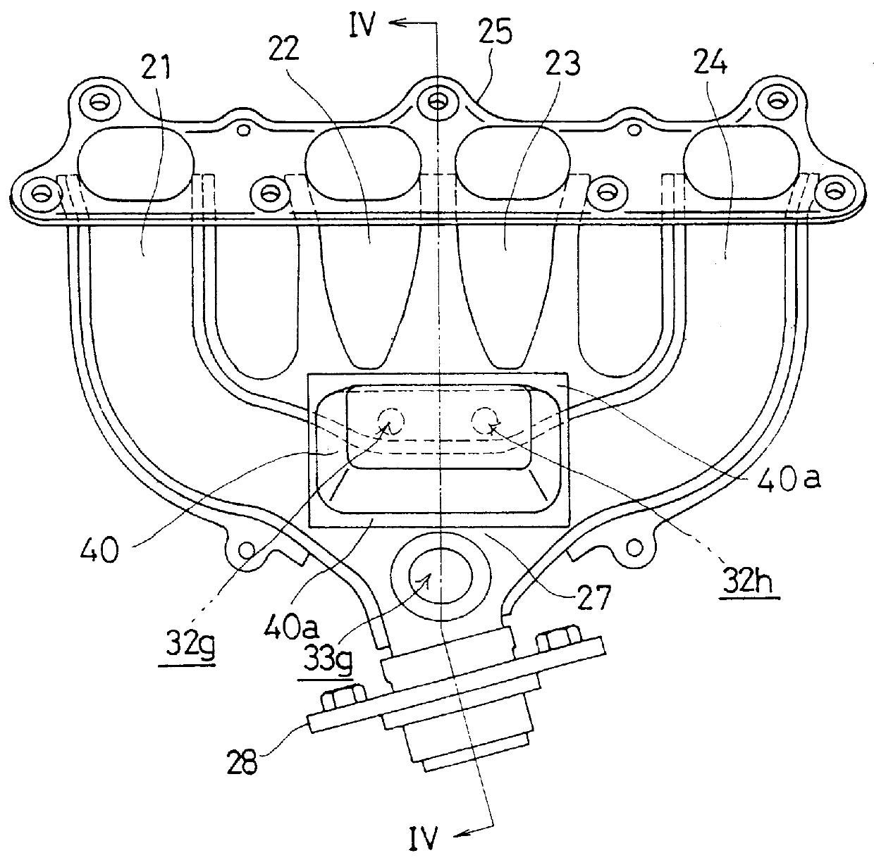
From a cylinder head 12 on the cylinder block 11, a suction manifold 15 extends forward and an exhaust manifold 20 extends rearward.

Provided four cylinders of the internal combustion engine 10 arranged in line laterally with respect to the car body are named respectively first, second, third and fourth cylinder in turn from the right side (right side when viewed facing in travelling direction of the car), the first and fourth cylinders constitute a cyl...


PUM

PropertyMeasurementUnit
Weightaaaaaaaaaa
Strengthaaaaaaaaaa

Abstract

An exhaust manifold made of plate metal in which sufficient strength and rigidity can be ensured, lightening of the weight is intended by making walls thin as a whole, and early activation of a catalyst is easy. The exhaust manifold is one for a multi-cylinder internal combustion engine having two groups of cylinders selected so that exhaust strokes are not successive. The exhaust manifold includes two exhaust pipe sections containing exhaust pipes communicating with the cylinders of one of the groups respectively, confluence sections where the exhaust pipes in each of the exhaust pipe sections join respectively, and a gathering section where the confluence sections join. Further, the exhaust manifold is constructed by an obverse half body, a partition body and a reverse half body made of plate metals and laid face to face with each other, the exhaust pipe sections and the confluence sections are formed by the partition body and one of the obverse and reverse half bodies, and the gathering section is formed by the obverse half body and the reverse half body.

Description

BACKGROUND OF THE INVENTIONThis invention relates to an exhaust manifold of a multi-cylinder internal combustion engine.In a multi-cylinder internal combustion engine, a construction that a plurality of cylinders are grouped in two groups in which exhaust strokes of cylinders are not successive and exhaust pipes communicating with the cylinders gather according to the respective groups is adopted in order to avoid an exhaust interference.An exhaust manifold of such construction is made of cast iron generally, but in order to reduce the weight, there has been proposed an exhaust manifold constructed by plate metal members laid face to face with each other.As an example thereof, an exhaust manifold described in Japanese Patent Publication No. Sho 63-26252 is shown in FIG. 12, which is an exploded view of the exhaust manifold 01. It is constituted by assembling three plate metal members, that is an upper side half body 02, a partition body 03 and a lower side half body 04, face to face...

Claims


Application Information

Patent Timeline
IPC IPC(8): F01N7/10F01N7/00F01N1/00F01N7/18F01N13/10F16L41/03
CPCF01N13/008F01N13/1888F01N13/10F01N1/00Y10T29/49398F01N2470/06
Inventor MATSUMOTO, SEIJI
Owner HONDA MOTOR CO LTD
Why Eureka
Try Eureka