Controller which controls a variable optical attenuator to control the power level of a wavelength-multiplexed optical signal when the number of channels are varied

a technology of variable optical attenuator and power level, which is applied in the field of fiber optic communication system, can solve the problems of non-linear degradation or s/n degradation of wavelength-multiplexed optical signals

Inactive Publication Date: 2000-02-15
FUJITSU LTD
View PDF12 Cites 106 Cited by
  • Summary
  • Abstract
  • Description
  • Claims
  • Application Information

AI Technical Summary

Benefits of technology

Accordingly, it is an object of the present invention to provide an optical amplifying apparatus which reduces non-linear degradation and S / N degradation of a wavelength-multiplexed optical signal when the number of channels are varied.
Objects of the present invention are also achieved by providing a method for controlling a light signal having a variable number of channels and amplified by an optical amplifier. The method includes the steps of: (a) prior to, and subsequent to, varying the number of channels in the light signal, passing the amplified light signal with a varying light transmissivity so that a power level of the amplified light signal is maintained at an approximately constant level in accordance with the number of channels in the light signal, and, (b) while the number of channels in the light signal is being varied, passing the amplified light signal with a constant light transmissivity.
Objects of the present invention are further achieved by providing an optical amplifier and a controller. The optical amplifier amplifies a light signal having a variable number of channels. Prior to, and subsequent to, varying the number of channels in the light signal, the controller maintains a power level of the amplified light signal at an approximately constant level in accordance with the number of channels in the light signal. While the number of channels in the light signal is being varied, the controller amplifies the amplified light signal with an approximately constant gain.

Problems solved by technology

Unfortunately, the use of a rare-earth doped optical fiber amplifier causes several problems when the number of channels in the wavelength-multiplexed optical signal is varied.
More specifically, during the variation (that is, before the variation in the number of channels is complete), the optical power of each channel can undesirably be varied, thereby causing non-linear degradation or S / N degradation of the wavelength-multiplexed optical signal.

Method used


Image

  • Controller which controls a variable optical attenuator to control the power level of a wavelength-multiplexed optical signal when the number of channels are varied
  • Controller which controls a variable optical attenuator to control the power level of a wavelength-multiplexed optical signal when the number of channels are varied
  • Controller which controls a variable optical attenuator to control the power level of a wavelength-multiplexed optical signal when the number of channels are varied

Examples


Embodiment Construction

Reference will now be made in detail to the present preferred embodiments of the present invention, examples of which are illustrated in the accompanying drawings, where like reference numerals refer to like elements throughout.

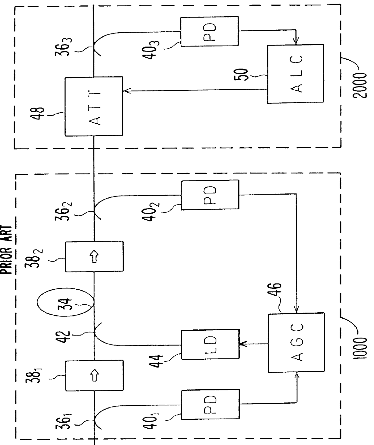
FIG. 2 is a diagram illustrating an optical amplifying apparatus for a fiber optic communication system which uses wavelength division multiplexing, and is similar to that disclosed in related to U.S. patent application Ser. No. 08 / 655,027, which is incorporated herein by reference.

Referring now to FIG. 2, the optical amplifying apparatus includes a first part 1000 (sometimes referred to herein as a "rare-earth-doped optical fiber amplifier part") and a second part 2000 (sometimes referred to herein as an "electrically-controlled optical device part").

First part 1000 includes a rare-earth-doped optical fiber (EDF) 34, optical branching couplers 36.sub.1 and 36.sub.2, optical isolators 38.sub.1 and 38.sub.2, photodiodes 40.sub.1 and 40.sub.2, an optical wavele...


PUM


Abstract

An optical amplifying apparatus which includes an optical amplifier, an optical attenuator and a controller. The optical amplifier amplifies a light signal having a variable number of channels. The optical attenuator passes the amplified light signal and has a variable light transmissivity. Prior to varying the number of channels in the light signal, the controller varies the light transmissivity of the optical attenuator so that a power level of the amplified light signal is maintained at an approximately constant level that depends on the number of channels in the light signal prior to the varying the number of channels. While the number of channels in the light signal is being varied, the controller maintains the light transmissivity of the optical attenuator to be constant. Subsequent to varying the number of channels in the light signal, the controller varies the light transmissivity of the optical attenuator so that a power level of the amplified light signal is maintained at an approximately constant level that depends on the number of channels in the light signal subsequent to the varying the number of channels.

Description

1. Field of the InventionThe present invention relates to a fiber optic communication system which uses wavelength division multiplexing to transmit a wavelength-multiplexed optical signal. More specifically, the present invention relates to a controller which controls an optical attenuator or an optical amplifier to change the power level of the wavelength-multiplexed optical signal when the number of channels are varied.2. Description of the Related ArtWavelength division multiplexing is used in fiber optic communication systems to transfer a relatively large amount of data at a high speed.FIG. 1 is a diagram illustrating a conventional fiber optic communication system which uses wavelength division multiplexing to transmit, for example, four channels through a single optical fiber. Referring now to FIG. 1, transmitting units 20-1, 20-2, 20-3 and 20-4 transmit individual carriers having wavelengths .lambda.1-.lambda.4, respectively. Each carrier is modulated with information and r...

Claims


Application Information

Patent Timeline
Patent Type & Authority Patents(United States)
IPC IPC(8): H01S3/067H01S3/13H01S3/06H04J14/02H04B10/17H01S3/10G02B6/06H04B10/07H04B10/2525H04B10/2543H04B10/29H04B10/296H04B10/54H04B10/564H04B10/58H04J14/00
CPCH01S3/06758H01S3/1301H04B10/291H04B10/2912H04B10/2931H04B10/2942H04B10/296H04J14/0221H01S3/10015H01S3/1003H01S2301/04H04B2210/003H01S3/13013
Inventor SUGAYA, YASUSHIKINOSHITA, SUSUMU
Owner FUJITSU LTD
Why Eureka
Try Eureka