Method and apparatus for producing direct reduced iron with improved reducing gas utilization

Inactive Publication Date: 2000-02-22
HYLSA SA DE CV
View PDF8 Cites 54 Cited by
  • Summary
  • Abstract
  • Description
  • Claims
  • Application Information

AI Technical Summary

Benefits of technology

It is therefore an object of the present invention to provide a method and an apparatus for producing direct reduced iron in a reduction system where quality of the recycle gas is enhanced by a more effective removal of reaction products from the recycle gas and an increase in the amount of hydrogen recycled to the reactor.
It is a further object of the present invention to provide a method and an apparatus for producing direct reduced iron in a reduction system where the p

Problems solved by technology

In the prior art of the direct reduction processes, there is no teaching or suggestion to recover H.sub.2 (and/or CO) from the gas purge, and especially there is no such teaching to do so by using physical adsor

Method used


Image

  • Method and apparatus for producing direct reduced iron with improved reducing gas utilization
  • Method and apparatus for producing direct reduced iron with improved reducing gas utilization
  • Method and apparatus for producing direct reduced iron with improved reducing gas utilization

Examples


Example

EXAMPLE

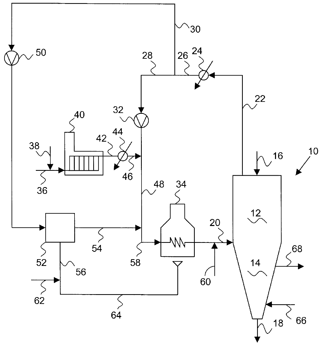
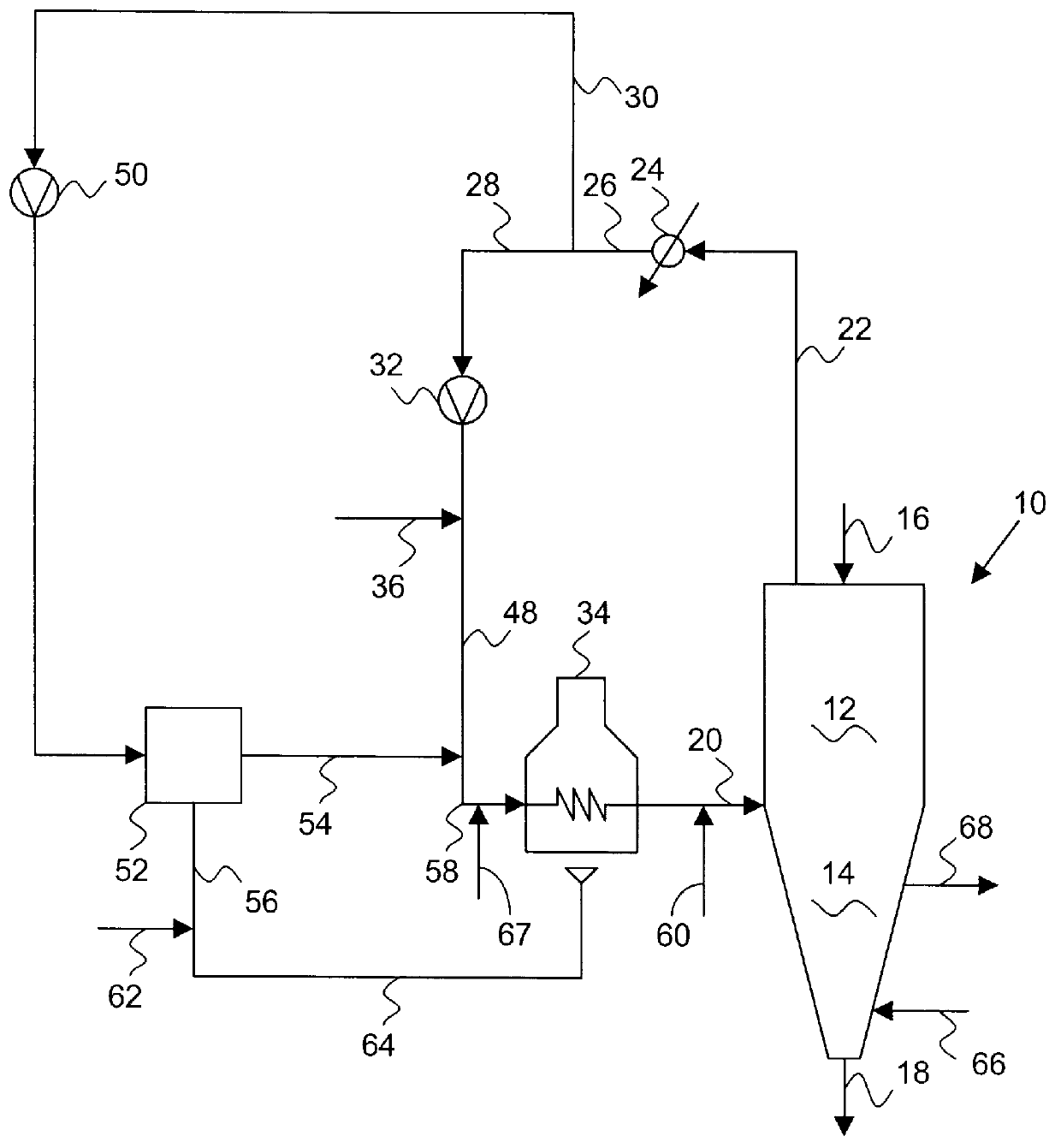
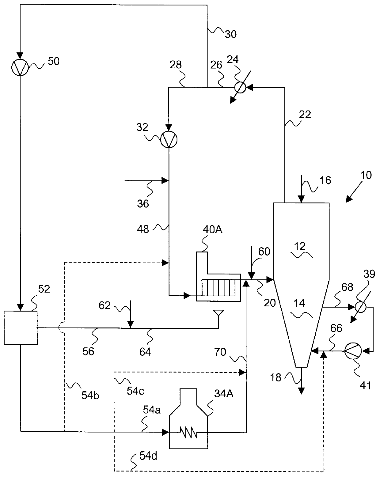
An example of the claimed process as calculated for potential implementation of an existing reduction system of the type illustrated in FIG. 1 (but with a cooling gas loop and natural gas feed thereto, as in FIG. 6). This is described as follows. A reducing gas 46 produced in steam-natural gas reformer 40 has the following composition on a dry basis in volume %:

H.sub.2 : 50% to 60%

CO: 30% to 37%

CO.sub.2 : 2% to 3.5%

CH.sub.4 : 1% to 3%

N.sub.2 : 0% to 1.5%

with the rest being lesser amounts of other hydrocarbons and inert gases.

This gas is fed as make up to the reduction system as stream 46. About 50% of the top gas 26 from the reduction zone is diverted as stream 30, with a composition on a dry basis in volume % as follows:

H.sub.2 : 35% to 45%

CO: 18% to 25%

CO.sub.2 : 10% to 20%

CH.sub.4 : 2% to 4%

N.sub.2 : 0% to 3%.

This is compressed and passed through a PSA adsorption system 52. A gas stream 54 is obtained with a hydrogen content in volume % on a dry basis between of 92% and 99...


PUM

PropertyMeasurementUnit
Fractionaaaaaaaaaa
Fractionaaaaaaaaaa
Angleaaaaaaaaaa

Abstract

A method and apparatus for producing DRI, prereduced materials, or the like, utilized in the steelmaking industry, where hydrogen contained in the gas stream purged from the reduction reactor is separated (preferably by means of a PSA system) and recycled to said reduction reactor. The productivity of the reduction plant is increased by using the separated hydrogen as a chemical reductant in the reactor, instead of using it as fuel. This is particularly useful in upgrading existing DRI production plants.

Description

The present invention relates to a method and apparatus for the production of prereduced iron ore, Direct Reduced Iron (DRI), or the like, in an reduction system comprising a reduction reactor, a source of natural gas, which is transformed in the operation of said system by means of a reformer and / or by the catalytic action of the metallic iron within said reduction reactor, to a reducing gas having carbon monoxide and hydrogen as its main constituents, and a heating device for heating said reducing gas prior to its introduction into the reduction zone of said reduction reactor. More particularly the invention relates to a method and apparatus which allows for a higher utilization of the chemical reduction potential of the reducing gas in the reduction system with a corresponding increase in the productivity of said reduction reactor or a decrease in the make-up quantity of gas needed for a given production level. This invention provides a way for increasing productivity of existing...

Claims


Application Information

Patent Timeline
IPC IPC(8): C21B13/00C21B13/02
CPCC21B13/02Y02P10/122C21B13/029C21B2100/26C21B2100/64C21B2100/44C21B2100/28C21B2100/282Y02P10/134Y02P10/20
Inventor VILLARREAL-TREVINO, JUAN A.
Owner HYLSA SA DE CV
Why Eureka
Try Eureka