Osseo-integrated sub-periosteal implant

a technology of osseointegration and implant, which is applied in the field of improved dental implant system, can solve the problems of inability to hold the intended position, dentures that are significantly less functional and subject to replacement, and uncomfortable, expensive and time-consuming process, etc., and achieves the enhancement of the support structure of the dental prosthesis, the effect of improving the strength and longevity of the system

Inactive Publication Date: 2000-02-29
ROBINSON DANE Q
View PDF11 Cites 99 Cited by
  • Summary
  • Abstract
  • Description
  • Claims
  • Application Information

AI Technical Summary

Benefits of technology

It is a more particular object of this invention to provide such an improved dental implant system in which the framework is much more securely implanted and therefore provides corresponding improved strength, health and longevity of the system.
It is a still more particular object of this invention to provide such an improved dental implant system in which, during the process of implanting the series of support posts, growth of a patient's bony ridge under and around a framework s

Problems solved by technology

However, such conventional dentures, which are held in place frictionally (and, to some extent, by suction and sometimes by the supplementary employment of special adhesive powder or paste), often are subject to failure to hold their intended positions.
This failure mode, which can increase in frequency as a person's gum structures alter over a period of time, subject the wearer to embarrassment and eventually render the dentures significantly less functional and subject to replacement.
However, this is an uncomfortable, expensive and time consuming process which may not be suitable for many dental patients due to a lack of available bone.
However, a significant problem with denture systems which employ support posts to engage and hold specially-configured dentures in place is the underlying security of the support posts.
There may be, at the time of emplacement or later, insecurity at the bases o

Method used


Image

  • Osseo-integrated sub-periosteal implant
  • Osseo-integrated sub-periosteal implant
  • Osseo-integrated sub-periosteal implant

Examples


Embodiment Construction

)

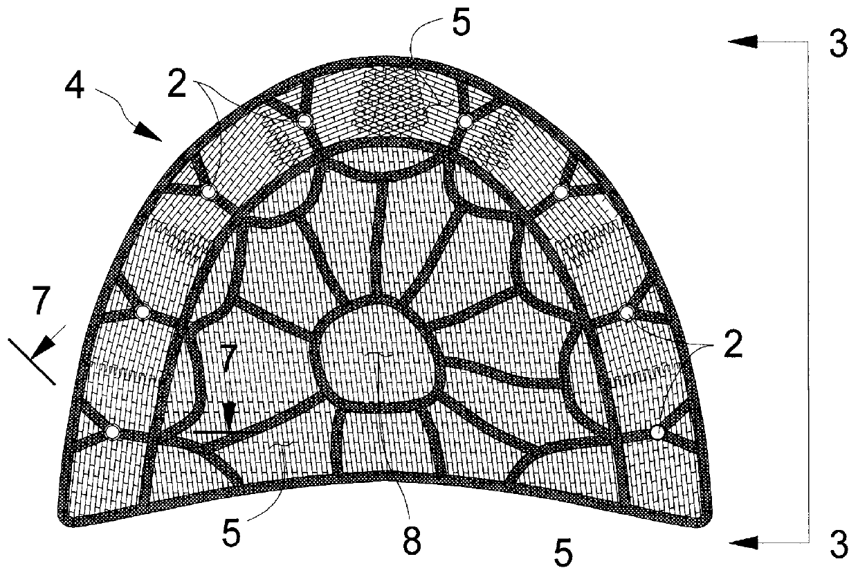
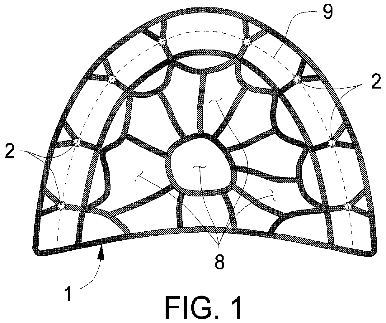
Attention is first directed to FIG. 1 which illustrates a first version of an important component of the inventive apparatus. More particularly, there is shown in FIG. 1, a plan view of a framework 1 of a prosthesis support structure suitable for use in the maxillary position and which serves to both provide a series of support posts 2 for a receiving a detachable denture and to promote growth of the maxillary bony ridge of a patient to which the prosthesis support structure has been fitted. Preferably, each of the support posts 2 is supported at the junction of framework members at the apex 9 of the framework. As will become more evident below, the under side of framework 1 fits intimately against the existing bone. The framework 1 extends into a palate abutment region 8 to provide additional rigidity and security when in place. The individual framework members may be joined in any suitable manner such as by the use of an adhesive, by welding (particularly spot welding) or sinteri...


PUM

PropertyMeasurementUnit
Structureaaaaaaaaaa
Bioabsorbableaaaaaaaaaa

Abstract

A sub-periosteally implantable prosthesis support structure for a fixed or detachable dental prosthesis includes a framework fitted to and generally conforming to the inner and outer contours of the bony ridge structures of a person. The framework is configured to provide a space extending generally normal to the bony ridge structure to an apex to provide space for subsequent bone growth. A plurality of denture support posts are distributed about the framework and depend outwardly from the apex in substantial alignment with the bony ridge structure. During the fabrication of the prosthesis support structure, a bio-compatible fine mesh screen is fixed to and spans, tent-like, the framework to substantially overlay the bone structure and the space provided for subsequent bone growth. After the support structure has been implanted, the growth of bone into the space and around the support structure is promoted to osseo-integrate the support structure with the person's bony ridge, thus providing a secure foundation for a denture or fixed dental prosthesis configured for detachable or fixed coupling with the denture support posts. The support structure may be made, partly or wholly, from either non-resorbable material, such as titanium stock and mesh, or from a resorbable material such as Vicryl TM .

Description

This invention relates to the art of dentistry and, more particularly, to devices which relate to the surgical placement of permanent dental support structures in the maxillary (upper) and mandibular (lower) jaw bones, which support structures are adapted to connectively receive complementarily-configured dental prostheses.For many years, persons who have lost their natural teeth have used full dentures as functional and aesthetic replacements. The most common configuration has been those dentures which have been individually fitted to a person's upper and lower gum structures as they exist at the time of fitting. When this procedure is carried out by a skillful dentist, with the assistance of a competent dental laboratory, the results can be satisfactory, at least for a time. However, such conventional dentures, which are held in place frictionally (and, to some extent, by suction and sometimes by the supplementary employment of special adhesive powder or paste), often are subject ...

Claims


Application Information

Patent Timeline
IPC IPC(8): A61C8/00A61F2/28A61F2/00A61F2/02A61F2/30
CPCA61C8/0006A61C8/0027A61C8/0031A61F2/2846A61F2/2803A61F2002/30062A61F2002/30329A61F2002/30448A61F2002/30451A61F2002/30456A61F2002/30892A61F2002/30909A61F2002/30957A61F2002/30968A61F2210/0004A61F2220/0025A61F2220/005A61F2220/0058A61F2310/00023
Inventor ROBINSON, DANE Q.
Owner ROBINSON DANE Q
Why Eureka
Try Eureka