Method for improving pattern bandwidth of shaped beam reflectarrays

a technology of reflectors and antennas, applied in the direction of individual energised antenna arrays, resonant antennas, radiating elements structural forms, etc., can solve the problems of reducing pattern bandwidth, degrading reflector bandwidth, and flat reflectors subject to two pattern bandwidth limitations, so as to reduce beamshape variations, improve the pattern bandwidth of a shaped beam reflector, and improve the effect of bandwidth limitations typically associated with previously known flat reflector arrangements

Inactive Publication Date: 2000-02-29
HUGHES ELECTRONICS
View PDF10 Cites 37 Cited by
  • Summary
  • Abstract
  • Description
  • Claims
  • Application Information

AI Technical Summary

Benefits of technology

The present invention overcomes abovementioned disadvantages by providing a method for improving the pattern bandwidth of a shaped beam reflectarray antenna. In general, the present invention overcomes the above-mentioned disadvantages by limiting the frequency variations in ray path electrical lengths so as to reduce beamshape variations over a frequency band. As a result, the bandwidth limitations typically associated with previously known flat reflectarray arrangements are substantially improved.
In the preferred embodiment, parabolic shaping of the reflector surface is employed in conjunction with the use of surface phasing elements, to reduce the ray path electrical length variations and collimate a shaped antenna beam. As a result, the substantial pattern bandwidth limitations associated with previously known reflectarrays are reduced. Furthermore, the present invention retains the forementioned cost and cycle time advantages since it utilizes a common reflector surface shape, preferably parabolic, to achieve customized beam shapes.
Thus, the present invention provides a method of improving bandwidth of a shaped beam pattern by combining geometric surface shaping with surface phasing on a reflectarray surface. In addition, the present invention provides a reflectarray for shaped beam antenna applications including a shaped surface, preferably parabolic in shape, to generate a focused beam via reflection of an impinging source beam and surface phasing elements carried by the shaped surface for configuring the focused beam.

Problems solved by technology

However, flat reflectarrays are subject to two pattern bandwidth limitations.
The first limitation is due to variations in ray path electrical lengths that are inherent to reflectarray systems.
The second limitation arises from reflectarray element phase variations as a function of the frequency of the wave impinging upon the element.
These elemental effects further degrade the reflectarray bandwidth.
As a result, attempts to configure the shape of the beam reflected from a reflectarray to a beam shape, defining a coverage area, are subject to losses that substantially reduce pattern bandwidth and thus limit the utility of the antenna for use over a band of frequencies.

Method used


Image

  • Method for improving pattern bandwidth of shaped beam reflectarrays
  • Method for improving pattern bandwidth of shaped beam reflectarrays
  • Method for improving pattern bandwidth of shaped beam reflectarrays

Examples


Embodiment Construction

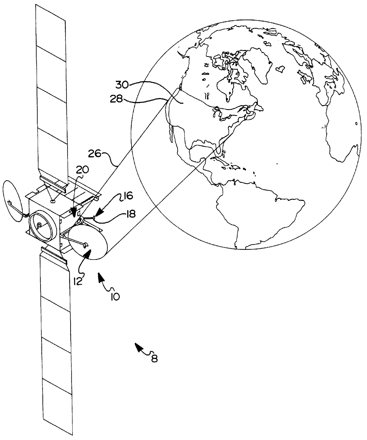
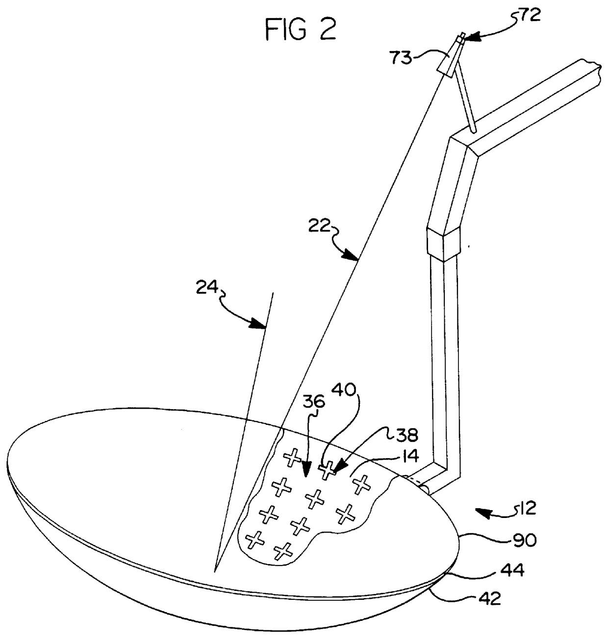
Referring first to FIG. 1, a satellite system 8 is shown with a payload communications system 10. The communication system 10 includes spaceborne, beam antenna 12 having a reflectarray surface, or surfaces 14 (FIG. 2). The communication system 10 operates in a signal transmission mode, a signal reception mode, or in both modes. Signal waves, preferably spherical waves, emanate from, or are collected at, feed point 16 including a feed 18 such as a wave guide horn 73 (FIG. 2). The feed 18 is connected to the radio frequency transmitter and / or receiver 20 in the system 10 via a transmission line such as waveguide or coaxial cable.

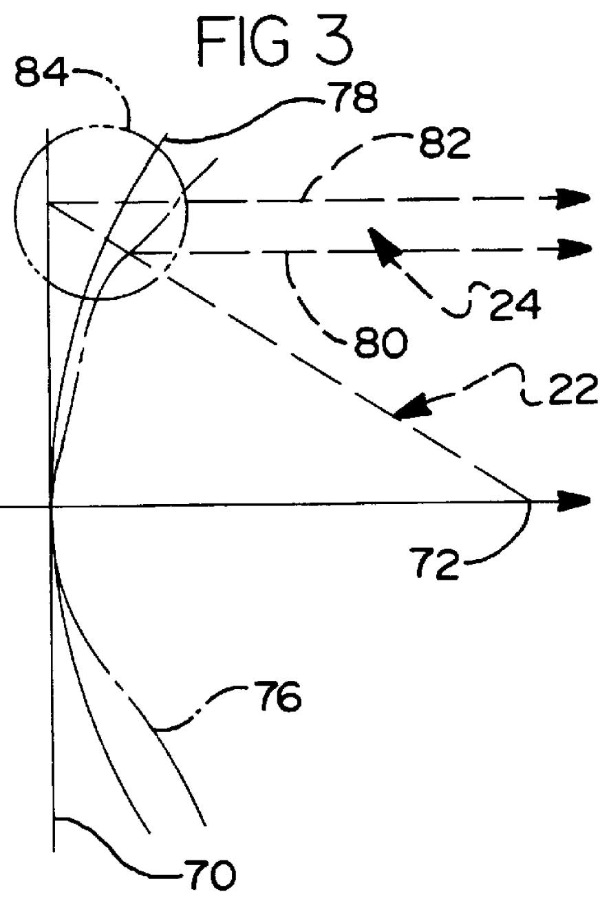
As shown in FIG. 2, ray path segments 22 and 24 indicate the relationship between the waves associated with the feed 18, the reflector surface 14, and the beam 26 (FIG. 1). In the transmission mode, the ray path segments 24 are focused by the reflectarray surface 14 to form a beam 26 (FIG. 1) collimated for coverage of a geographic reception area 28 (FIG. 1). ...


PUM


Abstract

A method for shaping reflected radio frequency signals includes geometrically shaping a reflector surface of an antenna to focus the beam, and reflectively shaping the reflector surface with phasing elements that emulate geometric shaping to configure the beam to a predetermined shape. In the preferred embodiment, the antenna comprises a geosynchronous satellite antenna conveying signals from a wave guide horn to or from a predetermined geographic area on earth. The use of a parabolic-approaching surface of reflectarray phasing elements for shaping the beam substantially improves the beam pattern bandwidth over the performance of previously known shaped beam reflectarrays.

Description

1. Field of the InventionThe present invention relates to reflectarray antennas for signal transmission to or reception from a geographic area whereby the reflectarray shapes the beam over the defined area.2. Background ArtRadio frequency communication signals are transmitted or received via antennas. For example, a satellite antenna in geosynchronous orbit is typically designed to cover a geographic area. Conventional parabolic reflectors have been physically reshaped to form beams which are collimated over specified geographical areas. Reflectarrays can also be designed to form beams collimated over specific geographical areas.Parabolic reflectors, when fed by a single radio frequency feed at the focus, generate pencil shaped beams. Optical techniques such as geometrical ray tracing demonstrate that all ray paths from the focus to any point on the reflector to the far field (on a reference plane), are of equal length. Consequently, such reflectors form focused pencil beams for all...

Claims


Application Information

Patent Timeline
Patent Type & Authority Patents(United States)
IPC IPC(8): H01Q3/46H01Q21/06H01Q3/26H01Q19/13H01Q3/00H01Q19/10H01Q15/16H01Q13/10
CPCH01Q3/2605H01Q3/46H01Q19/13H01Q21/062
Inventor COOLEY, MICHAEL E.CHWALEK, THOMAS J.RAMANUJAM, PARTHASARATH
Owner HUGHES ELECTRONICS
Why Eureka
Try Eureka