Light weight rotor and stator with multiple coil windings in thermal contact

Inactive Publication Date: 2000-03-07
COLEMAN POWERMATE
View PDF31 Cites 93 Cited by
  • Summary
  • Abstract
  • Description
  • Claims
  • Application Information

AI Technical Summary

Problems solved by technology

While referred to as portable, the prior art generator units tend to be heavy and u

Method used


Image

  • Light weight rotor and stator with multiple coil windings in thermal contact
  • Light weight rotor and stator with multiple coil windings in thermal contact
  • Light weight rotor and stator with multiple coil windings in thermal contact

Examples


Embodiment Construction

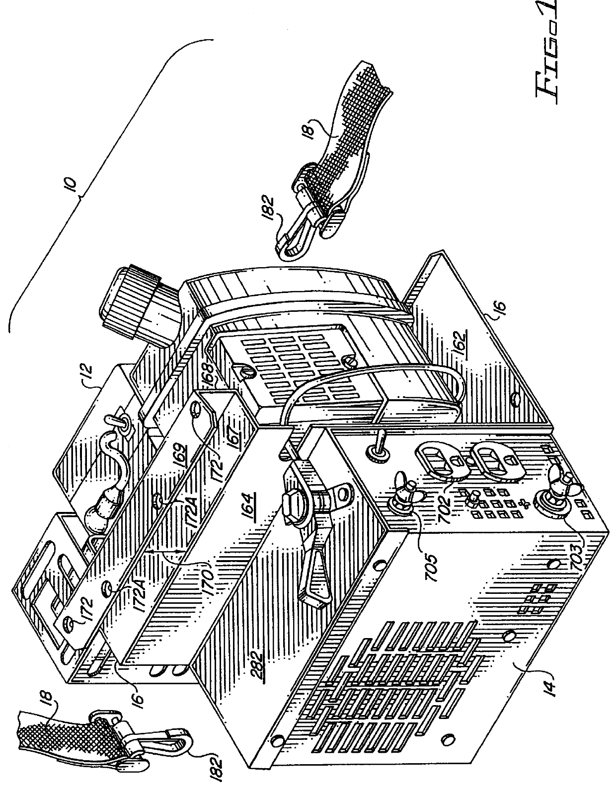
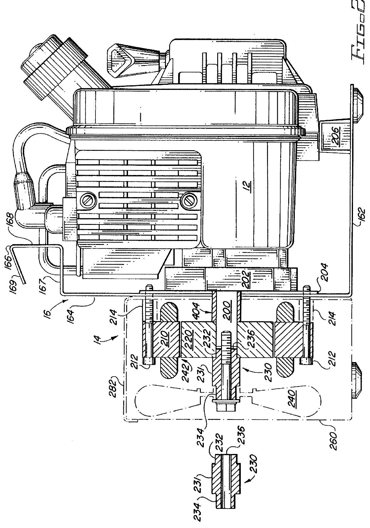
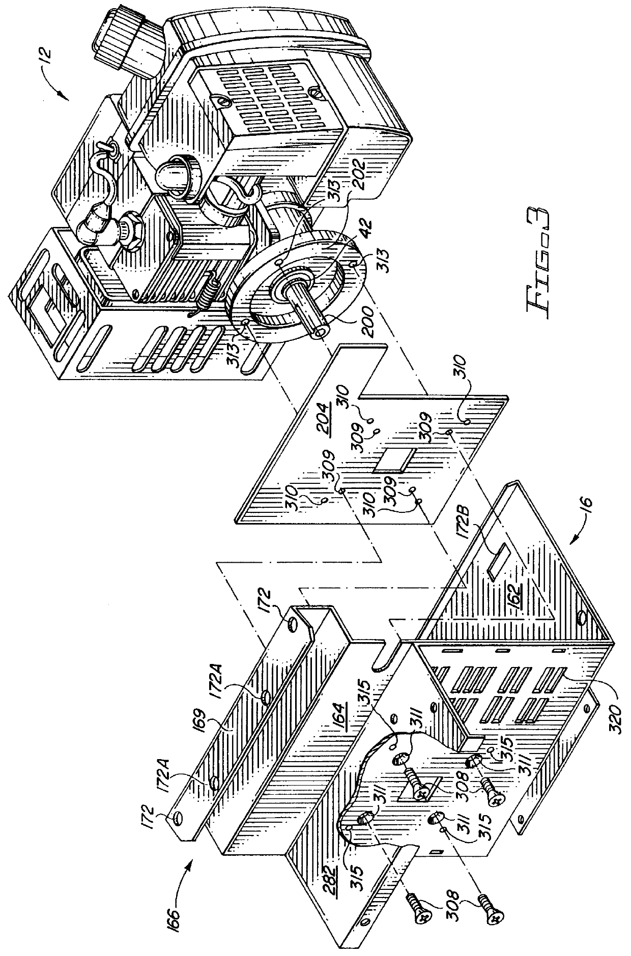
Referring to FIGS. 1 and 2, a lightweight portable generator embodying the present invention comprises an engine 12, a high output miniature generator unit 14, and a mounting frame 16.

As best seen in FIGS. 2 and 3, engine 12 suitably includes a shaft 200 extending outwardly from a shoulder 42. Engine 12 may be any small high RPM engine with a high horsepower to weight ratio capable of turning a shaft. In the preferred embodiment, engine 12 is a 2.0 horsepower, two-cycle internal combustion engine, having a displacement of 3 cubic inches and weighing 71 / 2 pounds, such as a Tecumseh TC300.

Referring now to FIGS. 1, 2 and 3, frame 16 provides a lightweight common mount for engine 12 and generator unit 14. Frame 16 is suitably formed of a lightweight rigid, electrically and thermally conductive material such as, for example, aluminum. In the preferred embodiment, an aluminum sheet is bent to provide foot 162, upright 164 and handle 166 portions of frame 16. The aluminum sheet is bent at ...


PUM


Abstract

A lightweight engine-driven generator set including a stator having at least first and second windings (preferably three-phase) and a rotor having a soft magnetic core and a plurality of high energy product permanent magnets, separated by consequence poles, disposed proximate the stator such that relative motion of the rotor and stator causes magnetic flux from the rotor to interact with and induce current in the stator windings. The first winding includes a predetermined number of turns corresponding to a first predetermined voltage output; and the second winding includes a predetermined number of turns corresponding to a second predetermined voltage output, the respective windings being grouped together as a unit and wound about the core such that the respective winding coils are wound in continuous close thermal contact with each other. The first winding generates a relatively high voltage, low amperage signal, and the second winding generates a relatively low voltage, high amperage signal; and a switch provides for selection of the desired output. Preferably the rotor is a hollow cylinder mounted on the engine shaft for rotation about the stator and such that the proper gap distance between rotor and stator is maintained during rotation of the rotor without bearings external to the engine. The low voltage, high amperage winding (or winding group) may be tapped to provide a selectable voltage output. Suitable rectifiers and inverters may be provided to effect selective DC and AC output signals.

Description

BACKGROUND OF INVENTIONThe present invention relates to lightweight portable electrical apparatus, and in particular, generators.In general, portable DC generators are known. Portable generators commonly comprise a conventional diesel or gasoline powered engine having a crankshaft coupled to a generator. The generator includes a stationary stator, and a rotor disposed for rotation with the engine shaft. The rotor generates a magnetic field. As the magnetic field intercepts windings on the stator, electrical current is induced. The induced current is typically applied to a bridge rectifier, sometimes regulated, and provided as an output. Examples of such prior art generators include the Generac G1000 (950 watts and 49 pounds), the Honda EX1000 (1000 watts and 57 pounds) and the Yamaha EF1000 (1000 watts and 55 pounds). While typically not found in portable units, an AC output can be provided by applying the DC signal to an inverter.While referred to as portable, the prior art generat...

Claims


Application Information

Patent Timeline
IPC IPC(8): F02B75/00F02B75/16F02B63/04F02B63/00H02K3/28H02K7/18H02K21/48H02K1/27H02K21/00H02K11/04H02P9/14H02P9/04H02P9/30H02K1/14H02K21/22H02K29/00
CPCF02B63/04F02B75/16H02K1/278H02K1/2786H02K3/28H02K7/1815H02K11/046H02K21/48H02P9/04H02P9/30H02P25/188H02P2101/45F02B2063/045F02B2063/046F05C2201/021F02B63/044H02M1/0085H02K11/05
Inventor SCOTT, HAROLD C.BEDNORZ, ARDEL R.JOHNSON, G. WEYLINANDERSON, WILLIAM JDAVIS, MITCHELL K.TALLY, HENRY
Owner COLEMAN POWERMATE
Why Eureka
Try Eureka