Differential pressure instrument support manifold having rotary mode selection system

a technology of mode selection system and differential pressure instrument, which is applied in the direction of instruments, fluid pressure measurement by mechanical elements, measurement devices, etc., can solve the problems of time-consuming and costly manual manipulation procedure, loss of revenue for the seller, and damage to sensitive differential pressure transmitters

Inactive Publication Date: 2000-03-14
HEWSON JOHN E
View PDF5 Cites 21 Cited by
  • Summary
  • Abstract
  • Description
  • Claims
  • Application Information

AI Technical Summary

Problems solved by technology

This manual manipulation procedure is time consuming and costly for the operator who must operate these valves in a specific sequence to obtain the zero condition and then return the manifold to the operating service in the specific reverse sequence.
If the zero and return sequences are not precisely followed, the sensitive differential pressure transmitter can be damaged.
In the "run" position, if the high differential pressure passage used to check zero were to leak from the high differential side to the low differential side, the resulting flow measurement would create an error and a loss of revenue for the seller.
Differential pres

Method used


Image

  • Differential pressure instrument support manifold having rotary mode selection system
  • Differential pressure instrument support manifold having rotary mode selection system
  • Differential pressure instrument support manifold having rotary mode selection system

Examples


Embodiment Construction

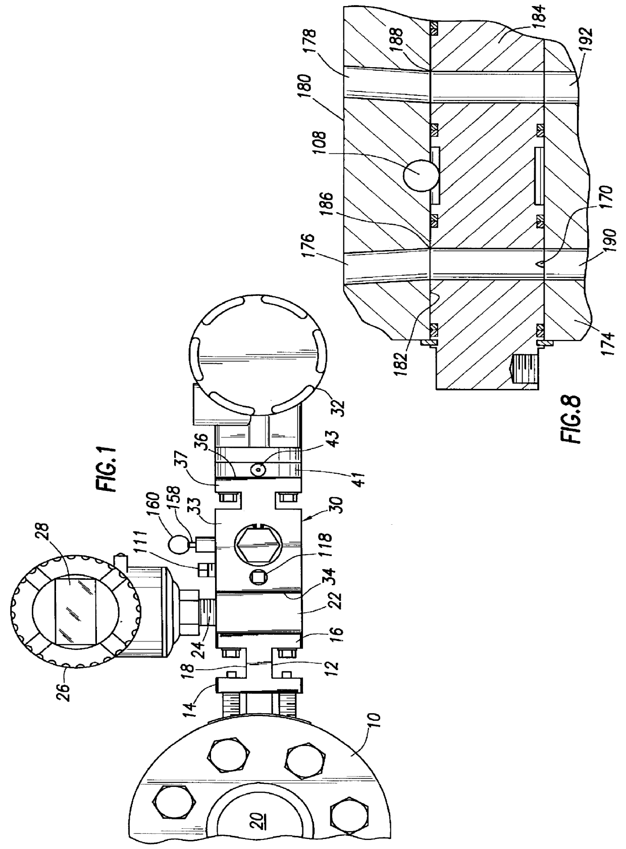
Referring now to the drawings and first to FIG. 1 a "process" is shown at 10 which, as is typical, is in the form of an orifice flange union / fitting having an internal orifice plate defining a circular orifice of specific dimension. To the orifice flange union / fitting is mounted a process interface support 12 having mounting flanges 14 and 16, the mounting flanges being integral with a web 18 having a pair of internal signal passages communicated with the flow passage 20 of the orifice flange union / fitting respectively on the upstream (high pressure side) and downstream (low pressure side) sides of the orifice plate. Thus, the signal pressures within the high pressure and low pressure signal passages will differ according to the differential pressure across the orifice plate of the orifice flange union / fitting 10. If desired, a mounting member 22 may be supported by the mounting flange 16 and will be provided with signal passage connectors 24 which conduct the high or low side stati...


PUM


Abstract

A spool type differential pressure transmitter support and valving manifold having a manifold body defining a process face and a transmitter face and having a generally cylindrical internal surface defining an open ended spool chamber and having signal inlet and outlet passages intersecting the process and transmitter faces and being in communication with the spool chamber. The manifold body also defines a vent passage which is in communication with said spool chamber. A spool member is positioned for rotation to "run", "zero" and "off" positions within the spool chamber, has ends extending from the open ends of the spool chamber and has a pair of transversely oriented body passages positioned for selective registry with the signal inlet and outlet passages at the "run" position of the spool member. Circumferential seals each preferably comprising an O-ring and a back-up ring establish sealing between the spool member and the manifold body and serve to isolate the signal passages from one another and to prevent leakage of signal pressure at the open ends of the spool chamber. A plurality of mode seal elements are carried by the outer periphery of the spool member and provide for manifold mode selection to the "run", "zero" and "off" positions responsive to rotational positioning of said spool member relative to said manifold body to permit calibration of the differential pressure transmitter with the pressurized process in operation.

Description

1. Field of the InventionThis invention relates to the valving means for instrument installations when flow measurement and / or control is desired in a fluid flow line using the differential pressure method for determining the flow rate. More particularly, the present invention concerns a rotary spool type instrument mounting and mode selecting manifold having a five-valve-function being "RUN", "ZERO--Lockup", "OFF--Lockup", "VENT" and "PURGE" and permitting simple and efficient calibration of a differential pressure transmitter instrument that is mounted thereto. Even more specifically, the present invention concerns a mounting and mode selection manifold providing instrument personnel with the capability of achieving "run", "zero" and "off / calibrate" functional modes simply by rotational settings of a rotary spool member of the manifold.2. Description of the Prior ArtThe differential pressure method of flow determination of such fluids as liquids, natural gas or other gases, and th...

Claims


Application Information

Patent Timeline
IPC IPC(8): G01L19/00
CPCG01L19/0015
Inventor HEWSON, JOHN E.
Owner HEWSON JOHN E
Why Eureka
Try Eureka