Probe coupler for ultrasound examination system

a technology of ultrasound examination system and probe coupler, which is applied in the field of ultrasound examination system, can solve the problems of low output power, low vibration frequency and output power, and difficulty in transmitting ultrasound signals to deeper parts of the patient's body

Inactive Publication Date: 2000-03-21
FUJI PHOTO OPTICAL CO LTD
View PDF5 Cites 21 Cited by
  • Summary
  • Abstract
  • Description
  • Claims
  • Application Information

AI Technical Summary

Problems solved by technology

Ultrasound transducer elements of small size which are high in vibration frequency and low in output power, however, have inherent problems such as a difficulty of transmitting ultrasound signals to deeper portions in patients body and weakness of return echoes which are susceptible to disturbances and deteriorations in the S / N ratio.
Nevertheless, the invention of this prior application is not exempted from all the problems which are encountered in practical use.
However, when a bulky end cap is used to accommodate an ultrasound transducer element of a large diameter, which is larger than the inside diameter of the outer tube, difficulties are encountered in separating and extracting the rotating part along with the connector member.
Besides, separation and extraction of the flexible shaft and electrodes through the distal end of the endoscopic insertion instrument become more difficult in case the electrodes are engaged with a stopper mechanism as mentioned above and increased in strength in addition to their square profiles.
Therefore, once the ultrasound probe is assembled into an operative state, it is often the case that rotating and stationary parts of the probe are not easily separable from each other, despite inconveniences in maintenance and service.

Method used


Image

  • Probe coupler for ultrasound examination system
  • Probe coupler for ultrasound examination system
  • Probe coupler for ultrasound examination system

Examples


Embodiment Construction

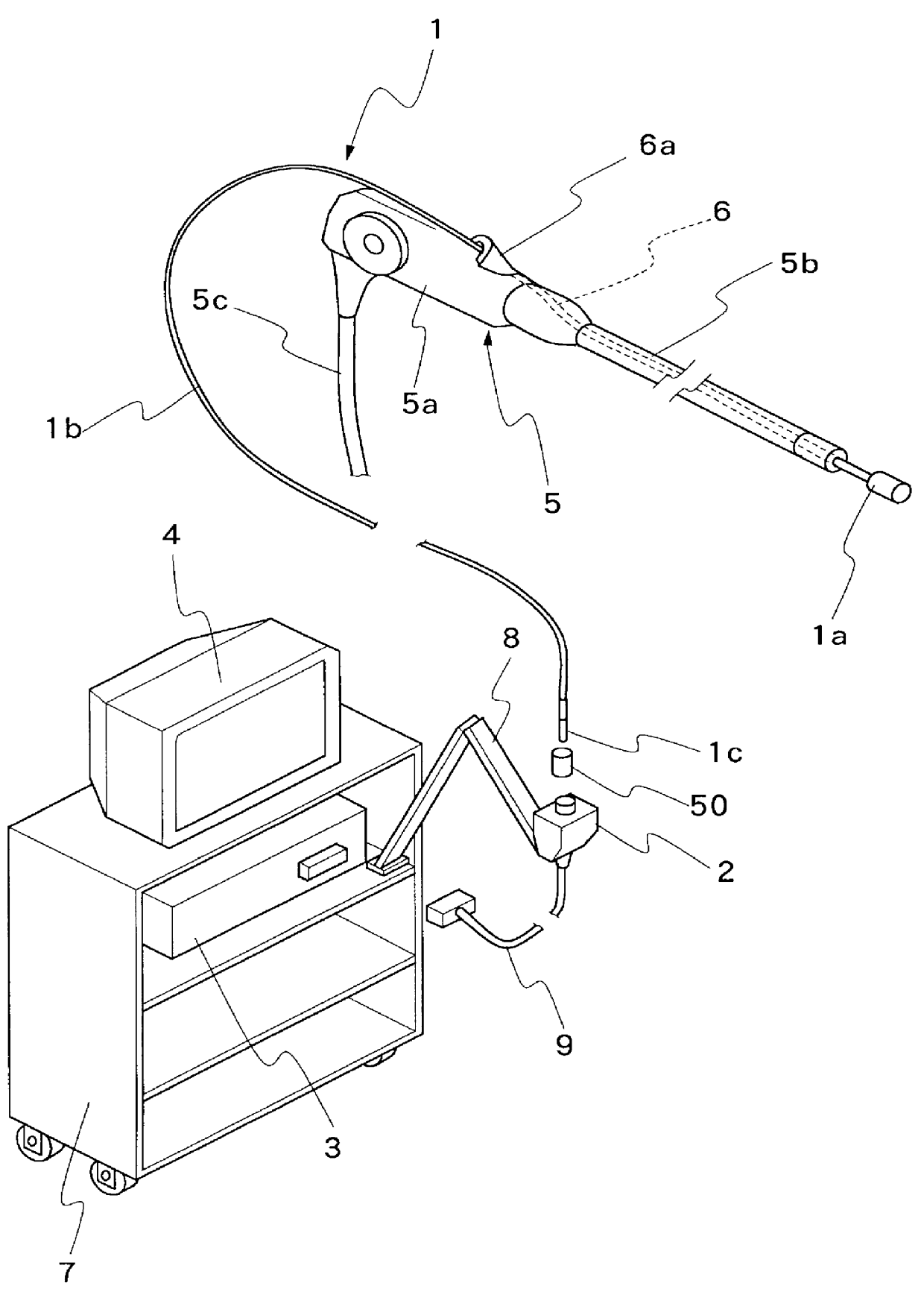
Hereafter, the present invention is described more particularly by way of its preferred embodiments shown in the drawings. Referring first to FIG. 1, there is schematically shown the general layout of an ultrasound examination system incorporating an ultrasound probe coupler according to the present invention. The ultrasound examination system is largely composed of an ultrasound probe 1, a probe control unit 2 and an ultrasound image observation terminal 3 with a monitor screen 4. The ultrasound probe 1 is of the type which is introduced into a body cavity by way of an endoscope 5, more specifically, by way of a biopsy channel 6 which is provided axially and internally of an endoscopic insertion instrument 5a and accessible through an entrance housing 6a, which is provided on a manipulating head grip 5a of the endoscope 5. Led out from the manipulating head grip 5a of the endoscope 5 is a universal cable 5c to be connected to a light source and an ultrasound signal processor which ...


PUM


Abstract

An ultrasound probe coupler for electrically and rotationally coupling an ultrasound probe with a probe control unit of an ultrasound examination system. The probe coupler essentially includes a tail end connector provided at the tail end of a flexible cord to be connected to the probe control unit. The tail end connector is provided with a stationary ring which is fixedly connected to a tail end portion of the flexible cord, and a rotational coupler having a series of rotary rings, including at least one electrode ring, for coupling the flexible shaft with a rotational drive means and an electrode on the part of the probe control unit. The rotational coupler further includes a rotation transmission member detachably connected to one of the rotating electrode rings and projected radially outward of the inner periphery of the stationary ring for engagement with a rotational drive member on the part of the probe control unit.

Description

FIELD OF THE ARTThis invention relates generally to an ultrasound examination system with a radial scan type ultrasound probe, having an ultrasound scanner to be put in rotation within a body cavity to make ultrasound scans in the rotational direction, and more particularly to a probe coupler for electrically and rotationally coupling an ultrasound probe with a probe control unit, the probe coupler permitting to disassemble rotating component parts of the ultrasound probe from stationary components easily whenever necessary.PRIOR ARTWith regard to ultrasound examination systems of the sort as mentioned above, it has been known to employ an endoscopically inserting ultrasound probe, which is designed to be inserted into a body cavity through a biopsy channel or an instrument channel of an endoscope, for example, as disclosed in U.S. Pat. Nos. 4,802,487 and 5,211,176. Ultrasound examination systems of this sort are largely constituted by an ultrasound probe member, a probe control uni...

Claims


Application Information

Patent Timeline
Patent Type & Authority Patents(United States)
IPC IPC(8): A61B8/12G10K11/00G10K11/35A61B1/00
CPCA61B8/12A61B8/4461G10K11/004G10K11/355A61B8/445
Inventor SAKAMOTO, TOSHIOTANAKA, TOSHIZUMIITOI, HIROMUYOSHIHARA, MASATOSHI
Owner FUJI PHOTO OPTICAL CO LTD
Why Eureka
Try Eureka