Sensor package arrangement

a sensor and package technology, applied in the field of sensor package arrangement, can solve the problems of extreme physical environment in which the sensor must work, affecting the accuracy of the acceleration output signal, and the requirement of vacuum packaging, etc., and achieves the effect of high external shock and simple installation

Inactive Publication Date: 2000-03-21
I O SENSORS
View PDF18 Cites 162 Cited by
  • Summary
  • Abstract
  • Description
  • Claims
  • Application Information

AI Technical Summary

Benefits of technology

Another object of the invention is to provide an accelerometer/enclosure arrangement which is rugged, simple to install, and re

Problems solved by technology

Furthermore, the physical environment in which the sensor must work is extreme.
However, the difference in the thermal expansion of different materials (silicon support frame, solder attach material and ceramic packages) can induce strain to the silicon electrode surface thereby distorting the accuracy of the acceleration output signal especially where specifications of -40.degree. C. to +85.degree. C. operating temperatures are required.
Vacuum packa

Method used


Image

  • Sensor package arrangement
  • Sensor package arrangement
  • Sensor package arrangement

Examples


Embodiment Construction

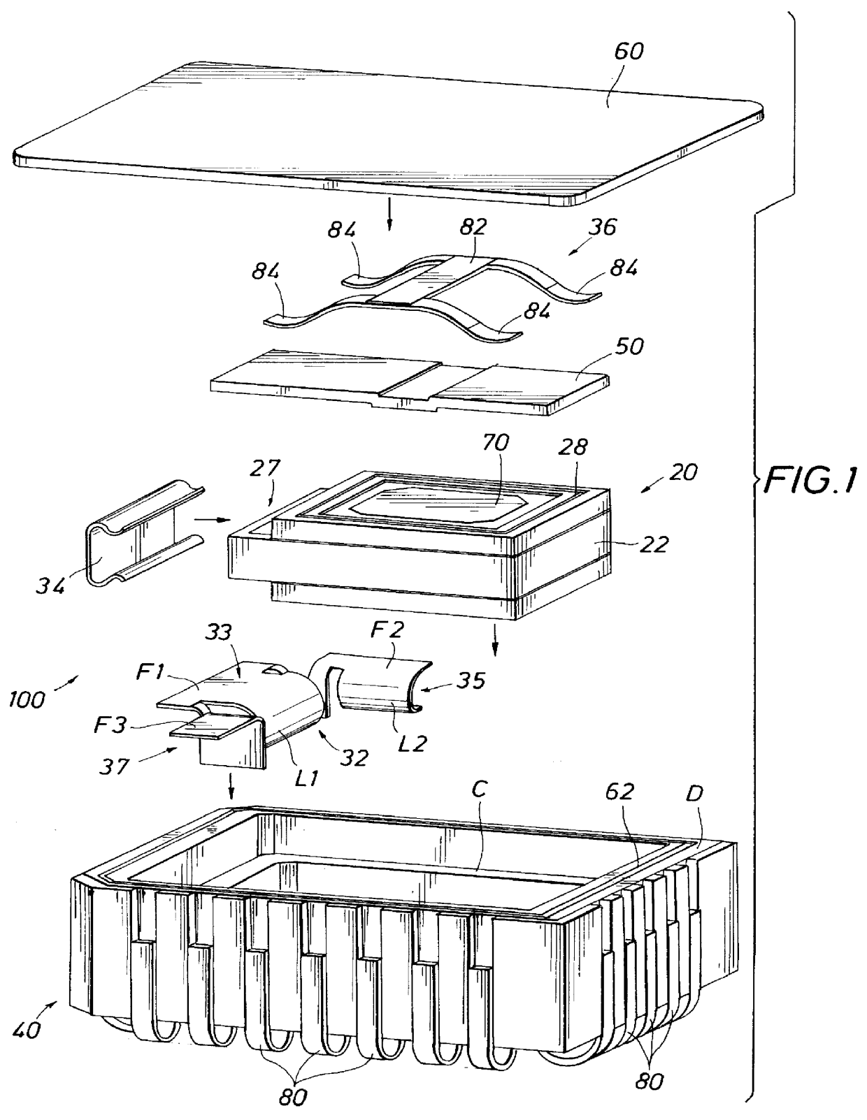
FIG. 1 shows an exploded view of the sensor / packaging arrangement 100 of the invention. A ceramic case 40 is provided to enclose the sensor die 20. A center contact spring 32 is inserted first into the ceramic case 40. (Also see FIG. 8 for an enlarged view of spring 32). A shorting clip 34 is installed on a projecting end 27 of center section 22 of the sensor 20. The sensor 20 with shorting clip 34 is placed into the ceramic case. A getter 50 and top contact spring 36 are secured to the bottom side of lid 60 and after vacuum evacuation, the lid 60 is secured on top of the ceramic case 40 while pressing downwardly on top contact spring 36 and the sensor die 20. Details of the elements of the assembly and their cooperative arrangement with each other follows.

Description of Ceramic Case 40

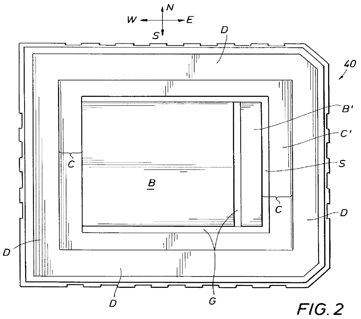
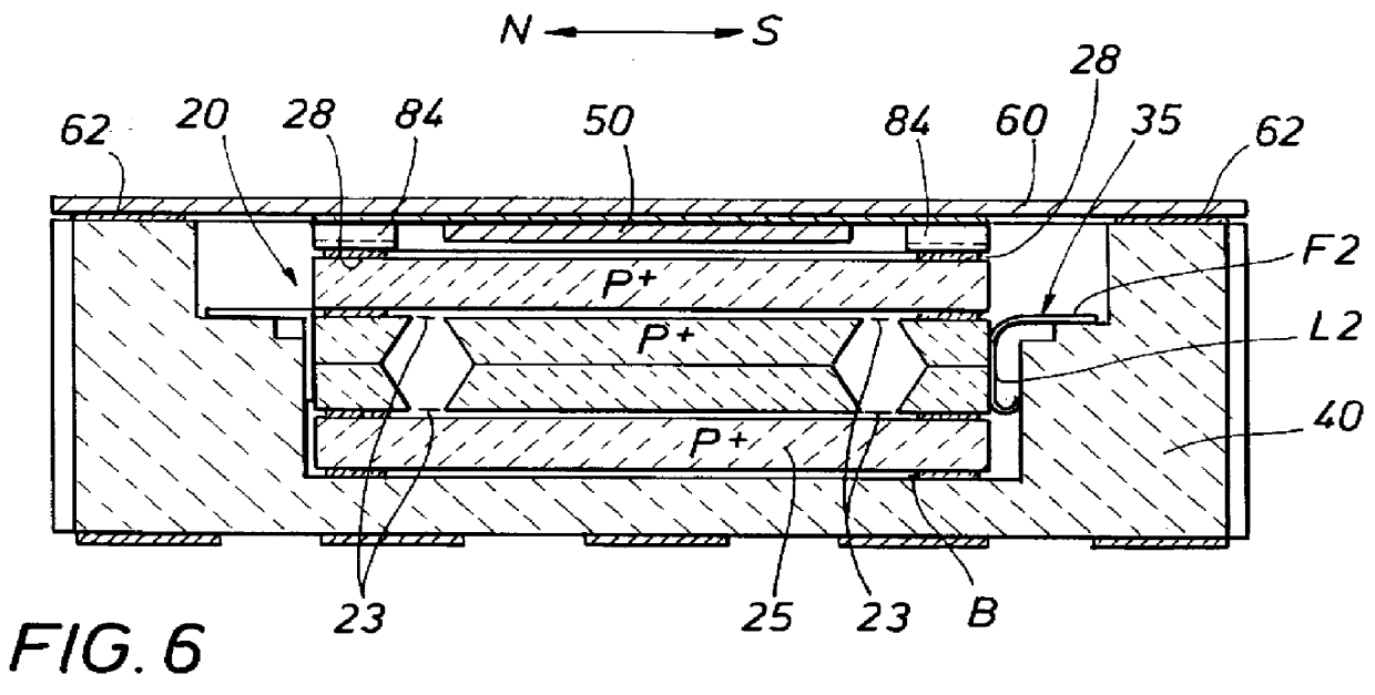
FIGS. 1, 2, 4, 5A, 5B, 5C and 6 illustrate ceramic case 40 in which sensor die 20 is placed. Ceramic case 40 is a multilayer co-fire alumina leadless chip carrier. The interior or cavity of case 40 ha...


PUM


Abstract

A highly sensitive silicon micro-machined sensor package is provided for use in a micro-g environment that can also resist high shock in excess of 5000 g. The sensor is provided to measure acceleration in cooperation with associated electronics which are required to have electrical contact with sensor elements. The sensor is sealed in a high vacuum environment, and is arranged and designed to be free of temperature induced stress to the sensor. The sensor die package assembly comprises a silicon micro-machined sensor die, a ceramic package, two contact springs, a shorting clip, solder preform, a metal lid and a getter foil for ensuring a good vacuum for an extended period. The sensor die comprises a moving mass with eight supporting flexures on both sides of the proof mass. The proof mass's movement is protected on both sides by a top and a bottom cap. Acceleration applied to the package and the die causes the proof mass to move vertically in relation with the adjacent caps. The changes in distance between the proof mass and the caps in turn generate a change in an electrical signal which corresponds to the capacitance changes between the gaps. The sensor die package arrangement provides that the sensor die be secured within an evacuated ceramic case. Electrical connections made between external contacts of the case and contacts of the sensor die within the case are made through conductive springs, thereby minimizing materials in the interior of the case which would outgass in the vacuum environment.

Description

1. Field of the InventionThis invention relates generally to packaging arrangement for a sensor. In particular the invention relates to a packaging arrangement including a case for a micro-machined-semi-conductor sensor die which establishes electrical contact between electrical leads of the sensor die and external contacts of the case, and for immobilizing the die within the case. Still more particularly the invention relates to a packaging arrangement in which a sensor die is electrically connected to outside contacts and secured within an evacuated cavity of a case without organic materials of any kind inside the cavity.2. Description of the Prior ArtThe sensor die to be packaged is a micro-machined device manufactured from silicon and arranged and designed to measure acceleration along a principal axis. The sensor includes a moving proof silicon mass supported from a surrounding frame of silicon by eight supporting springs on top and bottom sides of the proof mass. The proof mas...

Claims


Application Information

Patent Timeline
IPC IPC(8): B81B7/00G01P1/02G01P1/00G01P15/125
CPCB81B7/007G01P1/023G01P15/125H01L2924/0002H01L2924/00
Inventor IP, MATTHEW W.
Owner I O SENSORS
Why Eureka
Try Eureka